Toyota CH-R Service Manual: Inspection
INSPECTION
PROCEDURE
1. INSPECT REAR DOOR LOCK WITH MOTOR ASSEMBLY LH
|
(a) Check the operation of the door lock motor. (1) Apply battery voltage and check the operation of the door lock motor. OK:
If the result is not as specified, replace the rear door lock with motor assembly LH. |
|
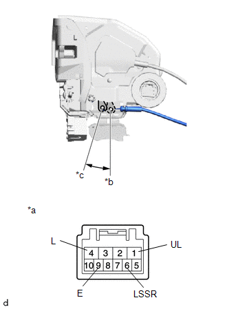
(b) Check the operation of the unlock detection switch.
(1) Measure the resistance according to the value(s) in the table below.
Standard Resistance:
|
Tester Connection |
Condition |
Specified Condition |
|---|---|---|
|
6 (LSSR) - 9 (E) |
Locked |
10 kΩ or higher |
|
6 (LSSR) - 9 (E) |
Unlocked |
Below 1 Ω |
If the result is not as specified, replace the rear door lock with motor assembly LH.
2. INSPECT REAR DOOR LOCK WITH MOTOR ASSEMBLY RH (w/o Double Locking System)
|
(a) Check the operation of the door lock motor. (1) Apply battery voltage and check the operation of the door lock motor. OK:
If the result is not as specified, replace the rear door lock with motor assembly RH. |
|
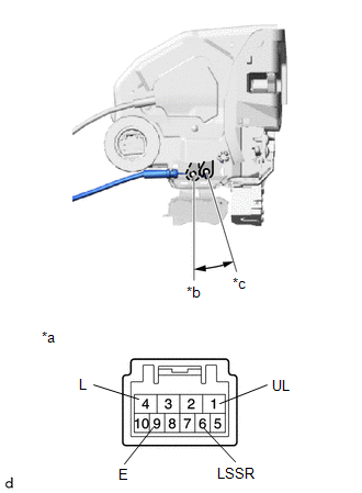
(b) Check the operation of the unlock detection switch.
(1) Measure the resistance according to the value(s) in the table below.
Standard Resistance:
|
Tester Connection |
Condition |
Specified Condition |
|---|---|---|
|
6 (LSSR) - 9 (E) |
Locked |
10 kΩ or higher |
|
6 (LSSR) - 9 (E) |
Unlocked |
Below 1 Ω |
If the result is not as specified, replace the rear door lock with motor assembly RH.
3. INSPECT REAR DOOR LOCK WITH MOTOR ASSEMBLY LH (w/ Double Locking System)
|
(a) Check the operation of the door lock motor and double lock motor. (1) Apply battery voltage and check the operation of the rear door lock motor and double lock motor. OK:
HINT:
If the result is not as specified, replace the rear door lock with motor assembly LH. |
|
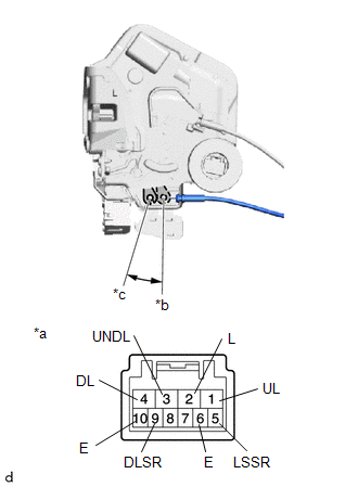
(b) Check the operation of the unlock detection switch and double lock position switch.
(1) Measure the resistance according to the value(s) in the table below.
Standard Resistance:
|
Tester Connection |
Condition |
Specified Condition |
|---|---|---|
|
5 (LSSR) - 6 (E) |
Locked |
10 kΩ or higher |
|
5 (LSSR) - 6 (E) |
Unlocked |
Below 1 Ω |
|
9 (DLSR) - 10 (E) |
Unset |
10 kΩ or higher |
|
9 (DLSR) - 10 (E) |
Set |
Below 1 Ω |
If the result is not as specified, replace the rear door lock with motor assembly LH.
4. INSPECT REAR DOOR LOCK WITH MOTOR ASSEMBLY RH (w/ Double Locking System)
|
(a) Check the operation of the door lock motor and double lock motor. (1) Apply battery voltage and check the operation of the rear door lock motor and double lock motor. OK:
HINT:
If the result is not as specified, replace the rear door lock with motor assembly RH. |
|
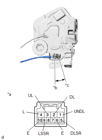
(b) Check the operation of the unlock detection switch and double lock position switch.
(1) Measure the resistance according to the value(s) in the table below.
Standard Resistance:
|
Tester Connection |
Condition |
Specified Condition |
|---|---|---|
|
9 (LSSR) - 10 (E) |
Locked |
10 kΩ or higher |
|
9 (LSSR) - 10 (E) |
Unlocked |
Below 1 Ω |
|
5 (DLSR) - 6 (E) |
Unset |
10 kΩ or higher |
|
5 (DLSR) - 6 (E) |
Set |
Below 1 Ω |
If the result is not as specified, replace the rear door lock with motor assembly RH.
 Components
COMPONENTS
ILLUSTRATION
*1
REAR DOOR INSIDE HANDLE BEZEL PLUG
*2
REAR DOOR REAR FRAME BRACKET
*3
REAR DOOR TRIM BOARD SUB-AS ...
 Removal
REMOVAL
CAUTION / NOTICE / HINT
The necessary procedures (adjustment, calibration, initialization, or registration)
that must be performed after parts are removed and installed, or replaced during ...
Other materials:
Toyota CH-R Service Manual > Lin Communication System: System Description
SYSTEM DESCRIPTION
LIN COMMUNICATION SYSTEM DESCRIPTION
The LIN communication system is used for communication between the components
in the tables below. If communication cannot be performed through LIN communication
such as when there is an open or short in a communication line, the master c ...
Toyota CH-R Service Manual > Power Window Control System: Jam Protection Function does not Operate
DESCRIPTION
This symptom may occur for any of the power windows.
The jam protection function operates within a specified range during the manual
up or auto up operation.
CAUTION / NOTICE / HINT
NOTICE:
If a power window regulator motor assembly has been replaced with a
new one, in ...
Toyota C-HR (AX20) 2023-2026 Owner's Manual
Toyota CH-R Owners Manual
- For safety and security
- Instrument cluster
- Operation of each component
- Driving
- Interior features
- Maintenance and care
- When trouble arises
- Vehicle specifications
- For owners
Toyota CH-R Service Manual
- Introduction
- Maintenance
- Audio / Video
- Cellular Communication
- Navigation / Multi Info Display
- Park Assist / Monitoring
- Brake (front)
- Brake (rear)
- Brake Control / Dynamic Control Systems
- Brake System (other)
- Parking Brake
- Axle And Differential
- Drive Shaft / Propeller Shaft
- K114 Cvt
- 3zr-fae Battery / Charging
- Networking
- Power Distribution
- Power Assist Systems
- Steering Column
- Steering Gear / Linkage
- Alignment / Handling Diagnosis
- Front Suspension
- Rear Suspension
- Tire / Wheel
- Tire Pressure Monitoring
- Door / Hatch
- Exterior Panels / Trim
- Horn
- Lighting (ext)
- Mirror (ext)
- Window / Glass
- Wiper / Washer
- Door Lock
- Heating / Air Conditioning
- Interior Panels / Trim
- Lighting (int)
- Meter / Gauge / Display
- Mirror (int)
- Power Outlets (int)
- Pre-collision
- Seat
- Seat Belt
- Supplemental Restraint Systems
- Theft Deterrent / Keyless Entry

0.0077