Toyota CH-R Service Manual: Components
COMPONENTS
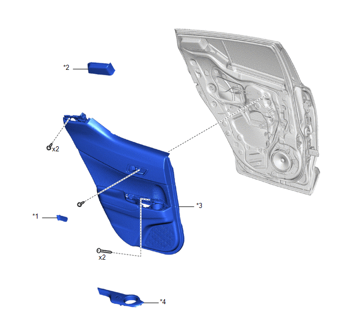
ILLUSTRATION
|
*1 |
REAR DOOR INSIDE HANDLE BEZEL PLUG |
*2 |
REAR DOOR REAR FRAME BRACKET |
|
*3 |
REAR DOOR TRIM BOARD SUB-ASSEMBLY |
*4 |
REAR POWER WINDOW REGULATOR SWITCH ASSEMBLY WITH REAR DOOR ARMREST BASE UPPER PANEL |
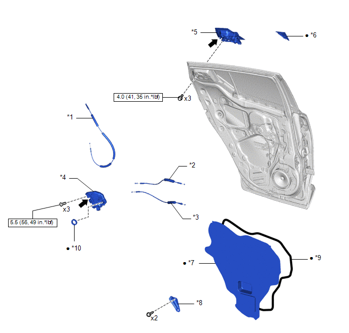
ILLUSTRATION
|
*1 |
NO. 1 REAR DOOR LOCK REMOTE CONTROL CABLE ASSEMBLY |
*2 |
REAR DOOR INSIDE LOCKING CABLE ASSEMBLY |
|
*3 |
REAR DOOR LOCK REMOTE CONTROL CABLE ASSEMBLY |
*4 |
REAR DOOR LOCK WITH MOTOR ASSEMBLY |
|
*5 |
REAR DOOR OUTSIDE HANDLE ASSEMBLY |
*6 |
REAR DOOR OUTSIDE HANDLE COVER |
|
*7 |
REAR DOOR SERVICE HOLE COVER |
*8 |
REAR DOOR TRIM BRACKET |
|
*9 |
BUTYL TAPE |
*10 |
DOOR LOCK WIRING HARNESS SEAL |
.png) |
N*m (kgf*cm, ft.*lbf): Specified torque |
● |
Non-reusable part |
.png) |
MP grease |
- |
- |
 Rear Door Lock
...
 Inspection
INSPECTION
PROCEDURE
1. INSPECT REAR DOOR LOCK WITH MOTOR ASSEMBLY LH
(a) Check the operation of the door lock motor.
(1) Apply battery voltage and check the operation of the door loc ...
Other materials:
Toyota CH-R Service Manual > Lighting System: Parts Location
PARTS LOCATION
ILLUSTRATION
*A
for LED Headlight
*B
w/ Fog Light
*C
w/ Door Mirror Foot Light
-
-
*1
FOG LIGHT ASSEMBLY RH
*2
FOG LIGHT ASSEMBLY LH
...
Toyota CH-R Service Manual > Door Control Switch: Installation
INSTALLATION
PROCEDURE
1. INSTALL MULTIPLEX NETWORK MASTER SWITCH ASSEMBLY (for Driver Side)
(a) Install the multiplex network master switch assembly with the 3 screws.
2. INSTALL DOOR CONTROL SWITCH ASSEMBLY (for Front Passenger Side)
(a) Engage the claws to install the door control ...
Toyota C-HR (AX20) 2023-2026 Owner's Manual
Toyota CH-R Owners Manual
- For safety and security
- Instrument cluster
- Operation of each component
- Driving
- Interior features
- Maintenance and care
- When trouble arises
- Vehicle specifications
- For owners
Toyota CH-R Service Manual
- Introduction
- Maintenance
- Audio / Video
- Cellular Communication
- Navigation / Multi Info Display
- Park Assist / Monitoring
- Brake (front)
- Brake (rear)
- Brake Control / Dynamic Control Systems
- Brake System (other)
- Parking Brake
- Axle And Differential
- Drive Shaft / Propeller Shaft
- K114 Cvt
- 3zr-fae Battery / Charging
- Networking
- Power Distribution
- Power Assist Systems
- Steering Column
- Steering Gear / Linkage
- Alignment / Handling Diagnosis
- Front Suspension
- Rear Suspension
- Tire / Wheel
- Tire Pressure Monitoring
- Door / Hatch
- Exterior Panels / Trim
- Horn
- Lighting (ext)
- Mirror (ext)
- Window / Glass
- Wiper / Washer
- Door Lock
- Heating / Air Conditioning
- Interior Panels / Trim
- Lighting (int)
- Meter / Gauge / Display
- Mirror (int)
- Power Outlets (int)
- Pre-collision
- Seat
- Seat Belt
- Supplemental Restraint Systems
- Theft Deterrent / Keyless Entry

0.0176