Toyota CH-R Service Manual: Components
COMPONENTS
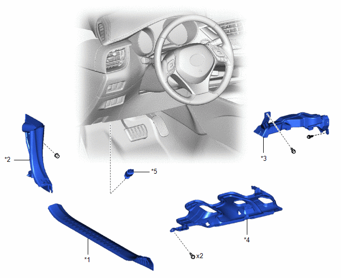
ILLUSTRATION
|
*1 |
COWL SIDE TRIM BOARD LH |
*2 |
FRONT DOOR SCUFF PLATE LH |
|
*3 |
NO. 1 AIR DUCT |
*4 |
NO. 1 INSTRUMENT PANEL UNDER COVER SUB-ASSEMBLY |
|
*5 |
STOP LIGHT SWITCH ASSEMBLY |
- |
- |

 On-vehicle Inspection
ON-VEHICLE INSPECTION
PROCEDURE
1. INSPECT STOP LIGHT SWITCH ASSEMBLY
(a) Disconnect the A45 stop light switch assembly connector.
...
Other materials:
Toyota CH-R Service Manual > Smart Key System(for Start Function): Data List / Active Test
DATA LIST / ACTIVE TEST
DATA LIST
HINT:
Using the Techstream to read the Data List allows the values or states of switches,
sensors, actuators and other items to be read without removing any parts. This non-intrusive
inspection can be very useful because intermittent conditions or signals may ...
Toyota CH-R Service Manual > Can Communication System: Check Bus 3 Lines for Short Circuit
DESCRIPTION
There may be a short circuit between the CAN main bus lines and/or CAN branch
lines when the resistance between terminals 6 (CA3H) and 21 (CA3L) of the central
gateway ECU (network gateway ECU) is below 54 Ω.
Symptom
Trouble Area
Resistance b ...
Toyota C-HR (AX20) 2023-2026 Owner's Manual
Toyota CH-R Owners Manual
- For safety and security
- Instrument cluster
- Operation of each component
- Driving
- Interior features
- Maintenance and care
- When trouble arises
- Vehicle specifications
- For owners
Toyota CH-R Service Manual
- Introduction
- Maintenance
- Audio / Video
- Cellular Communication
- Navigation / Multi Info Display
- Park Assist / Monitoring
- Brake (front)
- Brake (rear)
- Brake Control / Dynamic Control Systems
- Brake System (other)
- Parking Brake
- Axle And Differential
- Drive Shaft / Propeller Shaft
- K114 Cvt
- 3zr-fae Battery / Charging
- Networking
- Power Distribution
- Power Assist Systems
- Steering Column
- Steering Gear / Linkage
- Alignment / Handling Diagnosis
- Front Suspension
- Rear Suspension
- Tire / Wheel
- Tire Pressure Monitoring
- Door / Hatch
- Exterior Panels / Trim
- Horn
- Lighting (ext)
- Mirror (ext)
- Window / Glass
- Wiper / Washer
- Door Lock
- Heating / Air Conditioning
- Interior Panels / Trim
- Lighting (int)
- Meter / Gauge / Display
- Mirror (int)
- Power Outlets (int)
- Pre-collision
- Seat
- Seat Belt
- Supplemental Restraint Systems
- Theft Deterrent / Keyless Entry

0.0113