Toyota CH-R Service Manual: On-vehicle Inspection
ON-VEHICLE INSPECTION
PROCEDURE
1. INSPECT STOP LIGHT SWITCH ASSEMBLY
|
(a) Disconnect the A45 stop light switch assembly connector. |
|
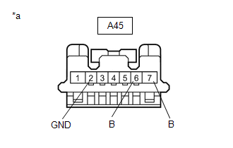
(b) Measure the voltage and resistance on the wire harness side connector according to the value(s) in the table below.
Standard Voltage:
|
Tester Connection |
Condition |
Specified Condition |
|---|---|---|
|
A45-7 (B) - A45-2 (GND) |
Ignition switch off |
11 to 14 V |
|
A45-6 (B) - A45-2 (GND) |
Ignition switch on (IG) |
11 to 14 V |
Standard Resistance:
|
Tester Connection |
Condition |
Specified Condition |
|---|---|---|
|
A45-2 (GND) - Body ground |
Always |
Below 1 Ω |
If the result is not as specified, repair or replace the wire harness or connector.
|
(c) Reconnect the A45 stop light switch assembly connector. |
|
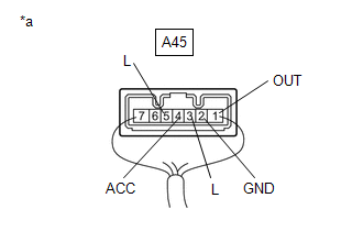
(d) Measure the voltage according to the value(s) in the table below.
Standard Voltage:
|
Tester Connection |
Condition |
Specified Condition |
|---|---|---|
|
A45- 1 (OUT) - A45-2 (GND) |
Ignition switch off, brake pedal not depressed |
Below 1 V |
|
A45-1 (OUT) - A45-2 (GND) |
Ignition switch off, brake pedal depressed |
11 to 14 V |
|
A45-3 (L) - A45-2 (GND) |
Ignition switch off, brake pedal not depressed |
Below 1 V |
|
A45-3 (L) - A45-2 (GND) |
Ignition switch off, brake pedal depressed |
11 to 14 V |
|
A45-4 (ACC) - A45-2 (GND) |
Ignition switch off |
11 to 14 V |
|
A45-5 (L) - A45-2 (GND) |
Ignition switch on (IG), brake pedal not depressed |
11 to 14 V |
|
A45-5 (L) - A45-2 (GND) |
Ignition switch on (IG), brake pedal depressed |
Below 1 V |
If the result is not as specified, replace the stop light switch assembly.
 Components
COMPONENTS
ILLUSTRATION
*1
COWL SIDE TRIM BOARD LH
*2
FRONT DOOR SCUFF PLATE LH
*3
NO. 1 AIR DUCT
*4
N ...
 Removal
REMOVAL
CAUTION / NOTICE / HINT
The necessary procedures (adjustment, calibration, initialization or registration)
that must be performed after parts are removed and installed, or replaced during ...
Other materials:
Toyota CH-R Service Manual > Blind Spot Monitor System: Short to GND in Outer Mirror Indicator(Master) (C1AB2)
DESCRIPTION
This DTC is stored when the blind spot monitor sensor LH (Master) detects a short
to ground in the outer rear view mirror indicator LH.
DTC No.
Detection Item
DTC Detection Condition
Trouble Area
C1AB2
Short to G ...
Toyota CH-R Service Manual > Brake Booster: On-vehicle Inspection
ON-VEHICLE INSPECTION
PROCEDURE
1. INSPECT BRAKE BOOSTER ASSEMBLY
(a) Airtightness check
(1) Start the engine and stop it after 1 or 2 minutes. Slowly depress
the brake pedal several times.
If the pedal can be depressed nearly to the floor the first time, but
on the 2nd and ...
Toyota C-HR (AX20) 2023-2026 Owner's Manual
Toyota CH-R Owners Manual
- For safety and security
- Instrument cluster
- Operation of each component
- Driving
- Interior features
- Maintenance and care
- When trouble arises
- Vehicle specifications
- For owners
Toyota CH-R Service Manual
- Introduction
- Maintenance
- Audio / Video
- Cellular Communication
- Navigation / Multi Info Display
- Park Assist / Monitoring
- Brake (front)
- Brake (rear)
- Brake Control / Dynamic Control Systems
- Brake System (other)
- Parking Brake
- Axle And Differential
- Drive Shaft / Propeller Shaft
- K114 Cvt
- 3zr-fae Battery / Charging
- Networking
- Power Distribution
- Power Assist Systems
- Steering Column
- Steering Gear / Linkage
- Alignment / Handling Diagnosis
- Front Suspension
- Rear Suspension
- Tire / Wheel
- Tire Pressure Monitoring
- Door / Hatch
- Exterior Panels / Trim
- Horn
- Lighting (ext)
- Mirror (ext)
- Window / Glass
- Wiper / Washer
- Door Lock
- Heating / Air Conditioning
- Interior Panels / Trim
- Lighting (int)
- Meter / Gauge / Display
- Mirror (int)
- Power Outlets (int)
- Pre-collision
- Seat
- Seat Belt
- Supplemental Restraint Systems
- Theft Deterrent / Keyless Entry

0.0065