Toyota CH-R Service Manual: Removal
REMOVAL
CAUTION / NOTICE / HINT
The necessary procedures (adjustment, calibration, initialization, or registration) that must be performed after parts are removed and installed, or replaced during the rear door lock with motor assembly removal/installation are shown below.
Necessary Procedure After Parts Removed/Installed/Replaced|
Replaced Part or Performed Procedure |
Necessary Procedure |
Effect/Inoperative when not Performed |
Link |
|---|---|---|---|
|
Disconnect cable from negative battery terminal |
Initialize back door lock |
Power door lock control system |
|
|
Memorize steering angle neutral point |
Lane departure alert system (w/ Steering Control) |
|
|
|
Pre-collision system |
|||
|
Initialize Power Window Control System |
|
|
HINT:
- Use the same procedure for the RH side and LH side.
- The following procedure is for the LH side.
PROCEDURE
1. PRECAUTION
NOTICE:
After turning the ignition switch off, waiting time may be required before disconnecting the cable from the negative (-) battery terminal. Therefore, make sure to read the disconnecting the cable from the negative (-) battery terminal notices before proceeding with work.
Click here
.gif)
2. DISCONNECT CABLE FROM NEGATIVE BATTERY TERMINAL
Click here
NOTICE:
When disconnecting the cable, some systems need to be initialized after the cable is reconnected.
Click here
3. REMOVE REAR DOOR REAR FRAME BRACKET
Click here
4. REMOVE REAR DOOR INSIDE HANDLE BEZEL PLUG
Click here
5. REMOVE REAR POWER WINDOW REGULATOR SWITCH ASSEMBLY WITH REAR DOOR ARMREST BASE UPPER PANEL
Click here
6. REMOVE REAR DOOR TRIM BOARD SUB-ASSEMBLY
Click here
7. REMOVE REAR DOOR TRIM BRACKET
Click here
8. REMOVE REAR DOOR SERVICE HOLE COVER
Click here
9. REMOVE REAR DOOR OUTSIDE HANDLE COVER
Click here
10. REMOVE REAR DOOR OUTSIDE HANDLE ASSEMBLY
Click here
11. REMOVE REAR DOOR LOCK WITH MOTOR ASSEMBLY
|
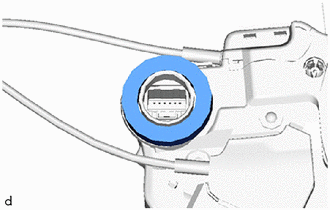
(a) Disconnect the connector. |
|
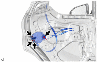
(b) Using a T30 "TORX" socket wrench, remove the 3 screws and rear door lock with motor assembly.
(c) When reusing the rear door lock with motor assembly:
|
(1) Remove the door lock wiring harness seal from the rear door lock with motor assembly. |
|
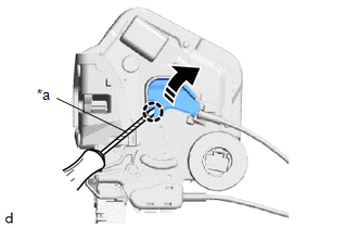
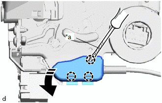
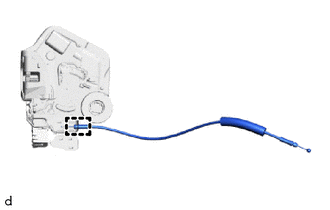
12. REMOVE REAR DOOR LOCK REMOTE CONTROL CABLE ASSEMBLY
(a) w/o Double Locking System:
(1) Using a screwdriver with its tip wrapped in protective tape, disengage the claw as shown in the illustration.
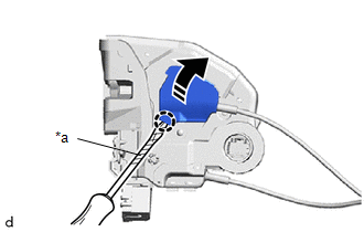
|
*a |
Protective Tape |
.png) |
Remove in this Direction |
|
(2) Disengage the guide to remove the rear door lock remote control cable assembly from the rear door lock with motor assembly. |
|
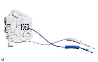
(b) w/ Double Locking System:
(1) Using a screwdriver with its tip wrapped in protective tape, disengage the claw as shown in the illustration.
|
*a |
Protective Tape |
|
|
Remove in this Direction |
|
(2) Disengage the guide to remove the rear door lock remote control cable assembly from the rear door lock with motor assembly. |
|
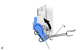
13. REMOVE REAR DOOR INSIDE LOCKING CABLE ASSEMBLY
(a) w/o Double Locking System:
(1) Using a screwdriver with its tip wrapped in protective tape, disengage the claws as shown in the illustration.
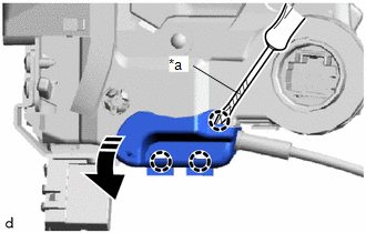
|
*a |
Protective Tape |
|
|
Remove in this Direction |
|
(2) Disengage the guide to remove the rear door inside locking cable assembly from the rear door lock with motor assembly. |
|
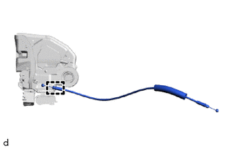
(b) w/ Double Locking System:
(1) Using a screwdriver with its tip wrapped in protective tape, disengage the claws as shown in the illustration.
|
*a |
Protective Tape |
|
|
Remove in this Direction |
|
(2) Disengage the guide to remove the rear door inside locking cable assembly from the rear door lock with motor assembly. |
|
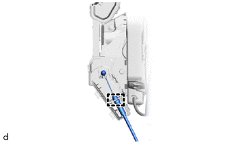
14. REMOVE NO. 1 REAR DOOR LOCK REMOTE CONTROL CABLE ASSEMBLY
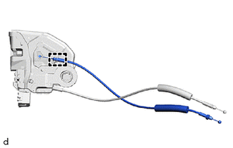
(a) Using a screwdriver with its tip wrapped in protective tape, disengage the claws as shown in the illustration.
|
*a |
Protective Tape |
|
|
Remove in this Direction |
|
(b) Disengage the guide to remove the No.1 rear door lock remote control cable assembly from the rear door lock with motor assembly. |
|
 Inspection
INSPECTION
PROCEDURE
1. INSPECT REAR DOOR LOCK WITH MOTOR ASSEMBLY LH
(a) Check the operation of the door lock motor.
(1) Apply battery voltage and check the operation of the door loc ...
 Installation
INSTALLATION
CAUTION / NOTICE / HINT
HINT:
Use the same procedure for the RH side and LH side.
The following procedure is for the LH side.
PROCEDURE
1. INSTALL NO. 1 REAR DOOR L ...
Other materials:
Toyota CH-R Service Manual > Power Steering System: Error in Matching of ECUs (C1567)
DESCRIPTION
Based on the steering sensor signal, the power steering ECU assembly determines
if the correct type of steering sensor is installed.
DTC No.
Detection Item
DTC Detection Condition
Trouble Area
Warning Indicate
Return-t ...
Toyota CH-R Service Manual > Power Steering System: TC and CG Terminal Circuit
DESCRIPTION
Connecting terminals TC and CG of the DLC3 causes the ECU to display DTCs by
blinking the EPS warning light.
WIRING DIAGRAM
CAUTION / NOTICE / HINT
NOTICE:
If the power steering ECU assembly has been replaced, perform assist map writing
and torque sensor zero point calibration ...
Toyota C-HR (AX20) 2023-2026 Owner's Manual
Toyota CH-R Owners Manual
- For safety and security
- Instrument cluster
- Operation of each component
- Driving
- Interior features
- Maintenance and care
- When trouble arises
- Vehicle specifications
- For owners
Toyota CH-R Service Manual
- Introduction
- Maintenance
- Audio / Video
- Cellular Communication
- Navigation / Multi Info Display
- Park Assist / Monitoring
- Brake (front)
- Brake (rear)
- Brake Control / Dynamic Control Systems
- Brake System (other)
- Parking Brake
- Axle And Differential
- Drive Shaft / Propeller Shaft
- K114 Cvt
- 3zr-fae Battery / Charging
- Networking
- Power Distribution
- Power Assist Systems
- Steering Column
- Steering Gear / Linkage
- Alignment / Handling Diagnosis
- Front Suspension
- Rear Suspension
- Tire / Wheel
- Tire Pressure Monitoring
- Door / Hatch
- Exterior Panels / Trim
- Horn
- Lighting (ext)
- Mirror (ext)
- Window / Glass
- Wiper / Washer
- Door Lock
- Heating / Air Conditioning
- Interior Panels / Trim
- Lighting (int)
- Meter / Gauge / Display
- Mirror (int)
- Power Outlets (int)
- Pre-collision
- Seat
- Seat Belt
- Supplemental Restraint Systems
- Theft Deterrent / Keyless Entry

0.0085