Toyota CH-R Service Manual: Installation
INSTALLATION
CAUTION / NOTICE / HINT
HINT:
- Use the same procedure for the RH side and LH side.
- The following procedure is for the LH side.
PROCEDURE
1. INSTALL FRONT DOOR INSIDE LOCKING CABLE ASSEMBLY
(a) w/o Double Locking System:
|
(1) Engage the guide to install the front door inside locking cable assembly to the front door lock with motor assembly. |
|
.png)
(b) w/ Double Locking System:
|
(1) Engage the guide to install the front door inside locking cable assembly to the front door lock with motor assembly. |
|
.png)
(2) Engage the claws as shown in the illustration.
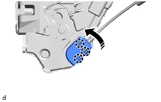
.png) |
Install in this Direction |
2. INSTALL FRONT DOOR LOCK REMOTE CONTROL CABLE ASSEMBLY
(a) w/o Double Locking System:
|
(1) Engage the guide to install the front door lock remote control cable assembly to the front door lock with motor assembly. |
|
(b) w/ Double Locking System:
|
(1) Engage the guide to install the front door lock remote control cable assembly to the front door lock with motor assembly. |
|
.png)
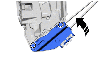
3. INSTALL FRONT DOOR LOCK COVER SUB-ASSEMBLY (w/o Double Locking System)
|
(a) Engage the guides to install the front door lock cover sub-assembly to the front door lock with motor assembly. |
|
.png)
(b) Engage the claws as shown in the illustration.
|
|
Install in this Direction |
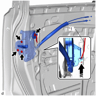
4. INSTALL FRONT DOOR LOCK WITH MOTOR ASSEMBLY
NOTICE:
- When reusing a removed front door lock with motor assembly, replace the door lock wiring harness seal with a new one.
- Do not allow grease or dust to adhere to the door lock wiring harness seal installation surface.
- Reusing a door lock wiring harness seal or using a damaged door lock wiring harness seal may cause water ingress. This may result in a malfunction of the front door lock with motor assembly.
(a) Apply MP grease to the sliding parts of the front door lock with motor assembly.
(b) When reusing the front door lock with motor assembly (w/o Double Locking System):
(1) Install a new door lock wiring harness seal to the front door lock with motor assembly.
(c) When reusing the front door lock with motor assembly (w/ Double Locking System):
(1) Install a new door lock wiring harness seal to the front door lock with motor assembly.
(d) Connect the front door lock open rod as shown in the illustration.
|
*1 |
Front Door Lock Open Rod |
|
|
Install in this Direction |
HINT:
Make sure that the front door lock open rod is securely connected to the front door lock with motor assembly.
(e) Using a T30 "TORX" socket wrench, install the front door lock with motor assembly with the 3 screws.
Torque:
5.5 N·m {56 kgf·cm, 49 in·lbf}
(f) Connect the connector.
5. INSTALL FRONT DOOR OUTSIDE HANDLE COVER (for Driver Side)
Click here
.gif)
6. INSTALL FRONT DOOR REAR LOWER FRAME SUB-ASSEMBLY
Click here
7. INSTALL FRONT DOOR GLASS RUN
Click here
8. INSTALL DOOR FRAME UPPER GARNISH
Click here
9. INSTALL FRONT DOOR GLASS SUB-ASSEMBLY
Click here
10. INSTALL FRONT DOOR SERVICE HOLE COVER
Click here
11. INSTALL FRONT DOOR BELT SEAL
Click here
12. INSTALL FRONT DOOR GLASS INNER WEATHERSTRIP
Click here
13. INSTALL FRONT DOOR TRIM BOARD SUB-ASSEMBLY
Click here
14. INSTALL POWER WINDOW REGULATOR SWITCH ASSEMBLY WITH FRONT ARMREST BASE UPPER PANEL (for Front Passenger Side)
Click here
15. INSTALL MULTIPLEX NETWORK MASTER SWITCH ASSEMBLY WITH FRONT ARMREST BASE UPPER PANEL (for Driver Side)
Click here
16. INSTALL FRONT DOOR INSIDE HANDLE BEZEL PLUG
Click here
17. CONNECT CABLE TO NEGATIVE BATTERY TERMINAL
Click here
NOTICE:
When disconnecting the cable, some systems need to be initialized after the cable is reconnected.
Click here
18. INITIALIZE POWER WINDOW CONTROL SYSTEM
Click here
19. INSPECT POWER WINDOW OPERATION
Click here
 Removal
REMOVAL
CAUTION / NOTICE / HINT
The necessary procedures (adjustment, calibration, initialization, or registration)
that must be performed after parts are removed and installed, or replaced during ...

Other materials:
Toyota CH-R Service Manual > Seat Belt Warning System(w/ Occupant Classification System): Parts Location
PARTS LOCATION
ILLUSTRATION
*1
BRAKE ACTUATOR ASSEMBLY (SKID CONTROL ECU)
*2
ECM
ILLUSTRATION
*1
MAIN BODY ECU (MULTIPLEX NETWORK BODY ECU)
*2
INSTRUMENT PANEL JUNCTION BLOCK ASSEMBLY
- ECU-DC ...
Toyota CH-R Service Manual > Audio And Visual System(for Radio Receiver Type): How To Proceed With Troubleshooting
CAUTION / NOTICE / HINT
HINT:
Use the following procedure to troubleshoot the audio and visual system.
PROCEDURE
1.
VEHICLE BROUGHT TO WORKSHOP
NEXT
2.
CUSTOMER PROBLEM ANALYS ...
Toyota C-HR (AX20) 2023-2026 Owner's Manual
Toyota CH-R Owners Manual
- For safety and security
- Instrument cluster
- Operation of each component
- Driving
- Interior features
- Maintenance and care
- When trouble arises
- Vehicle specifications
- For owners
Toyota CH-R Service Manual
- Introduction
- Maintenance
- Audio / Video
- Cellular Communication
- Navigation / Multi Info Display
- Park Assist / Monitoring
- Brake (front)
- Brake (rear)
- Brake Control / Dynamic Control Systems
- Brake System (other)
- Parking Brake
- Axle And Differential
- Drive Shaft / Propeller Shaft
- K114 Cvt
- 3zr-fae Battery / Charging
- Networking
- Power Distribution
- Power Assist Systems
- Steering Column
- Steering Gear / Linkage
- Alignment / Handling Diagnosis
- Front Suspension
- Rear Suspension
- Tire / Wheel
- Tire Pressure Monitoring
- Door / Hatch
- Exterior Panels / Trim
- Horn
- Lighting (ext)
- Mirror (ext)
- Window / Glass
- Wiper / Washer
- Door Lock
- Heating / Air Conditioning
- Interior Panels / Trim
- Lighting (int)
- Meter / Gauge / Display
- Mirror (int)
- Power Outlets (int)
- Pre-collision
- Seat
- Seat Belt
- Supplemental Restraint Systems
- Theft Deterrent / Keyless Entry

0.0088