Toyota CH-R Service Manual: Inspection
INSPECTION
PROCEDURE
1. INSPECT FRONT DOOR LOCK WITH MOTOR ASSEMBLY LH (w/o Double Locking System)
|
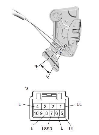
(a) Check the door lock motor operation (for Driver Side). (1) Apply battery voltage to the motor connector and check the operation of the door lock motor. OK:
HINT:
If the result is not as specified, replace the front door lock with motor assembly LH. |
|
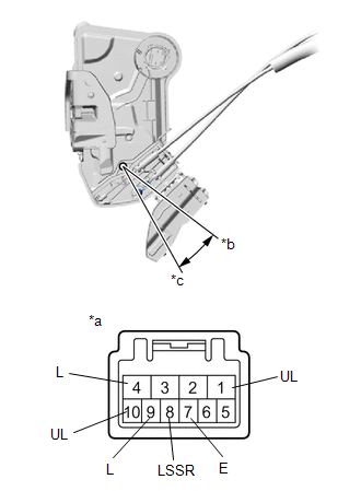
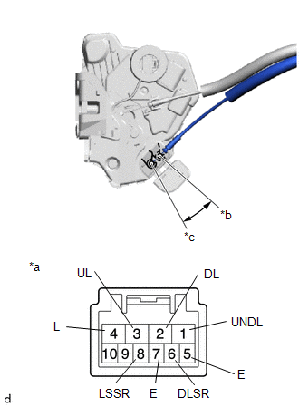
(b) Check the operation of the door unlock detection switch and double lock position switch (for Driver Side).
(1) Measure the resistance according to the value(s) in the table below.
Standard Resistance:
|
Tester Connection |
Condition |
Specified Condition |
|---|---|---|
|
8 (LSSR) - 7 (E) |
Lock |
10 kΩ or higher |
|
8 (LSSR) - 7 (E) |
Unlock |
Below 1 Ω |
|
9 (L) - 10 (UL) |
Unset |
10 kΩ or higher |
|
9 (L) - 10 (UL) |
Set |
Below 1 Ω |
If the result is not as specified, replace the front door lock with motor assembly LH.
|
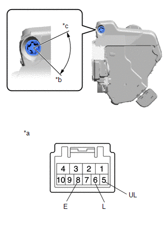
(c) Check the resistance of the lock and unlock switch (for Driver Side). (1) Measure the resistance according to the value(s) in the table below. Standard Resistance:
If the result is not as specified, replace the front door lock with motor assembly LH. |
|
|
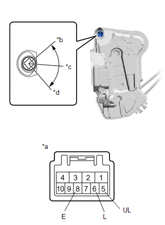
(d) Check the operation of the door lock motor (for Front Passenger Side). (1) Apply battery voltage to the motor connector and check the operation of the door lock motor. OK:
If the result is not as specified, replace the front door lock with motor assembly LH. |
|
(e) Check the operation of the door unlock detection switch (for Front Passenger Side).
(1) Measure the resistance according to the value(s) in the table below.
Standard Resistance:
|
Tester Connection |
Condition |
Specified Condition |
|---|---|---|
|
8 (LSSR) - 7 (E) |
Lock |
10 kΩ or higher |
|
8 (LSSR) - 7 (E) |
Unlock |
Below 1 Ω |
If the result is not as specified, replace the front door lock with motor assembly LH.
2. INSPECT FRONT DOOR LOCK WITH MOTOR ASSEMBLY RH (w/o Double Locking System)
|
(a) Check the operation of the door lock motor (for Front Passenger Side). (1) Apply battery voltage to the motor connector and check the operation of the door lock motor. OK:
If the result is not as specified, replace the front door lock with motor assembly RH. |
|
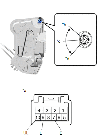
(b) Check the operation of the door unlock detection switch (for Front Passenger Side).
(1) Measure the resistance according to the value(s) in the table below.
Standard Resistance:
|
Tester Connection |
Condition |
Specified Condition |
|---|---|---|
|
7 (LSSR) - 8 (E) |
Locked |
10 kΩ or higher |
|
7 (LSSR) - 8 (E) |
Unlocked |
Below 1 Ω |
If the result is not as specified, replace the front door lock with motor assembly RH.
|
(c) Check the door lock motor operation (for Driver Side). (1) Apply battery voltage to the motor connector and check the operation of the door lock motor. OK:
HINT:
If the result is not as specified, replace the front door lock with motor assembly RH. |
|
(d) Check the operation of the door unlock detection switch and double lock position switch (for Driver Side).
(1) Measure the resistance according to the value(s) in the table below.
Standard Resistance:
|
Tester Connection |
Condition |
Specified Condition |
|---|---|---|
|
7 (LSSR) - 8 (E) |
Locked |
10 kΩ or higher |
|
7 (LSSR) - 8 (E) |
Unlocked |
Below 1 Ω |
|
5 (UL) - 6 (L) |
Unset |
10 kΩ or higher |
|
5 (UL) - 6 (L) |
Set |
Below 1 Ω |
If the result is not as specified, replace the front door lock with motor assembly RH.
|
(e) Check the resistance of the lock and unlock switch (for Driver Side). (1) Measure the resistance according to the value(s) in the table below. Standard Resistance:
If the result is not as specified, replace the front door lock with motor assembly RH. |
|
3. INSPECT FRONT DOOR LOCK WITH MOTOR ASSEMBLY LH (w/ Double Locking System)
|
(a) Check the door lock motor operation (for Driver Side). (1) Apply battery voltage and check the operation of the front door lock motor and double lock motor. OK:
HINT:
If the result is not as specified, replace the front door lock with motor assembly LH. |
|
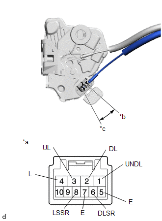
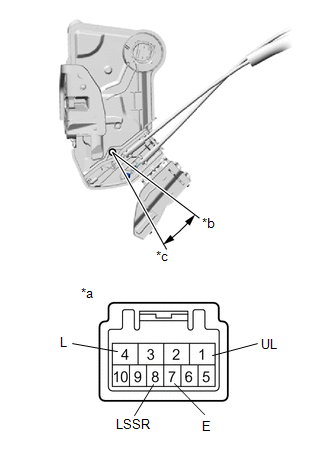
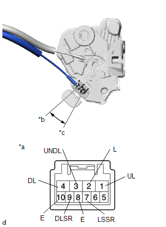
(b) Check the operation of the door unlock detection switch and double lock position switch (for Driver Side).
(1) Measure the resistance according to the value(s) in the table below.
Standard Resistance:
|
Tester Connection |
Condition |
Specified Condition |
|---|---|---|
|
8 (LSSR) - 7 (E) |
Lock |
10 kΩ or higher |
|
8 (LSSR) - 7 (E) |
Unlock |
Below 1 Ω |
|
6 (DLSR) - 5 (E) |
Unset |
10 kΩ or higher |
|
6 (DLSR) - 5 (E) |
Set |
Below 1 Ω |
If the result is not as specified, replace the front door lock with motor assembly LH.
|
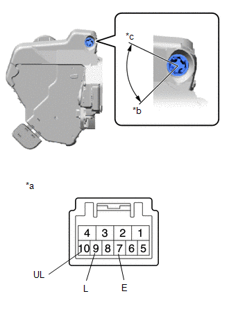
(c) Check the resistance of the lock and unlock switch (for Driver Side). (1) Measure the resistance according to the value(s) in the table below. Standard Resistance:
If the result is not as specified, replace the front door lock with motor assembly LH. |
|
|
(d) Check the operation of the door lock motor (for Front Passenger Side). (1) Apply battery voltage to the motor connector and check the operation of the door lock motor. OK:
HINT:
If the result is not as specified, replace the front door lock with motor assembly LH. |
|
(e) Check the operation of the door unlock detection switch and double lock position switch (for Front Passenger Side).
(1) Measure the resistance according to the value(s) in the table below.
Standard Resistance:
|
Tester Connection |
Condition |
Specified Condition |
|---|---|---|
|
8 (LSSR) - 7 (E) |
Lock |
10 kΩ or higher |
|
8 (LSSR) - 7 (E) |
Unlock |
Below 1 Ω |
|
6 (DLSR) - 5 (E) |
Unset |
10 kΩ or higher |
|
6 (DLSR) - 5 (E) |
Set |
Below 1 Ω |
If the result is not as specified, replace the front door lock with motor assembly LH.
4. INSPECT FRONT DOOR LOCK WITH MOTOR ASSEMBLY RH (w/ Double Locking System)
|
(a) Check the operation of the front door lock motor (for Front Passenger Side). (1) Apply battery voltage and check the operation of the front door lock motor and double lock motor. OK:
HINT:
If the result is not as specified, replace the front door lock with motor assembly RH. |
|

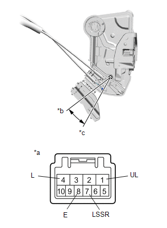
(b) Check the operation of the door unlock detection switch and double lock position switch (for Front Passenger Side).
(1) Measure the resistance according to the value(s) in the table below.
Standard Resistance:
|
Tester Connection |
Condition |
Specified Condition |
|---|---|---|
|
7 (LSSR) - 8 (E) |
Lock |
10 kΩ or higher |
|
7 (LSSR) - 8 (E) |
Unlock |
Below 1 Ω |
|
9 (DLSR) - 10 (E) |
Unset |
10 kΩ or higher |
|
9 (DLSR) - 10 (E) |
Set |
Below 1 Ω |
If the result is not as specified, replace the front door lock with motor assembly RH.
|
(c) Check the operation of the front door lock motor (for Driver Side). (1) Apply battery voltage and check the operation of the front door lock motor and double lock motor. OK:
HINT:
If the result is not as specified, replace the front door lock with motor assembly RH. |
|
(d) Check the operation of the door unlock detection switch and double lock position switch (for Driver Side).
(1) Measure the resistance according to the value(s) in the table below.
Standard Resistance:
|
Tester Connection |
Condition |
Specified Condition |
|---|---|---|
|
7 (LSSR) - 8 (E) |
Lock |
10 kΩ or higher |
|
7 (LSSR) - 8 (E) |
Unlock |
Below 1 Ω |
|
9 (DLSR) - 10 (E) |
Unset |
10 kΩ or higher |
|
9 (DLSR) - 10 (E) |
Set |
Below 1 Ω |
If the result is not as specified, replace the front door lock with motor assembly RH.
|
(e) Check the operation of the door key lock and unlock switch (for Driver Side). (1) Measure the resistance according to the value(s) in the table below. Standard Resistance:
If the result is not as specified, replace the front door lock with motor assembly RH. |
|
 Components
COMPONENTS
ILLUSTRATION
*A
for Driver Side
*B
for Front Passenger Side
*1
FRONT DOOR BELT SEAL
*2
FRON ...
 Removal
REMOVAL
CAUTION / NOTICE / HINT
The necessary procedures (adjustment, calibration, initialization, or registration)
that must be performed after parts are removed and installed, or replaced during ...
Other materials:
Toyota CH-R Service Manual > Rain Sensor: Components
COMPONENTS
ILLUSTRATION
*1
RAIN SENSOR
*2
RAIN SENSOR COVER
*3
RAIN SENSOR TAPE
-
-
...
Toyota CH-R Service Manual > Can Communication System: Data List / Active Test
DATA LIST / ACTIVE TEST
NOTICE:
In the table below, the values listed under "Normal Condition" are reference
values. Do not depend solely on these reference values when deciding whether a part
is faulty or not.
HINT:
Using the Techstream to read the Data List allows the values or s ...
Toyota C-HR (AX20) 2023-2026 Owner's Manual
Toyota CH-R Owners Manual
- For safety and security
- Instrument cluster
- Operation of each component
- Driving
- Interior features
- Maintenance and care
- When trouble arises
- Vehicle specifications
- For owners
Toyota CH-R Service Manual
- Introduction
- Maintenance
- Audio / Video
- Cellular Communication
- Navigation / Multi Info Display
- Park Assist / Monitoring
- Brake (front)
- Brake (rear)
- Brake Control / Dynamic Control Systems
- Brake System (other)
- Parking Brake
- Axle And Differential
- Drive Shaft / Propeller Shaft
- K114 Cvt
- 3zr-fae Battery / Charging
- Networking
- Power Distribution
- Power Assist Systems
- Steering Column
- Steering Gear / Linkage
- Alignment / Handling Diagnosis
- Front Suspension
- Rear Suspension
- Tire / Wheel
- Tire Pressure Monitoring
- Door / Hatch
- Exterior Panels / Trim
- Horn
- Lighting (ext)
- Mirror (ext)
- Window / Glass
- Wiper / Washer
- Door Lock
- Heating / Air Conditioning
- Interior Panels / Trim
- Lighting (int)
- Meter / Gauge / Display
- Mirror (int)
- Power Outlets (int)
- Pre-collision
- Seat
- Seat Belt
- Supplemental Restraint Systems
- Theft Deterrent / Keyless Entry

0.0078