Toyota CH-R Service Manual: Washer Nozzle(for Front Side)
Components
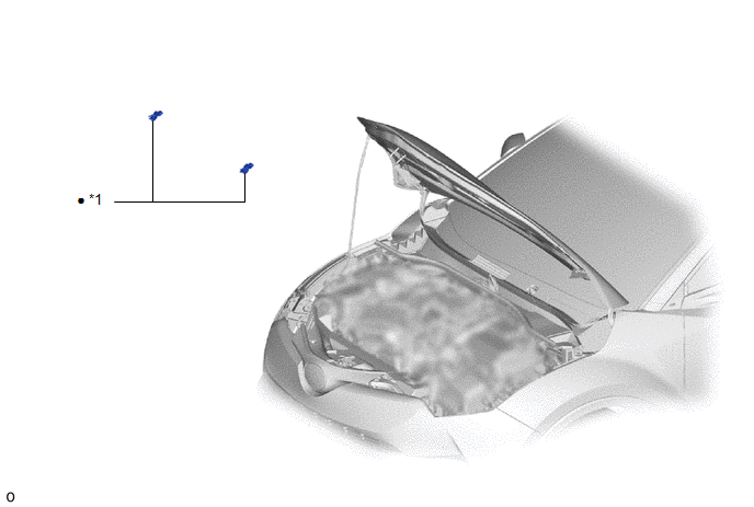
COMPONENTS
ILLUSTRATION
|
*1 |
WASHER NOZZLE SUB-ASSEMBLY |
- |
- |
|
● |
Non-reusable part |
- |
- |
On-vehicle Inspection
ON-VEHICLE INSPECTION
PROCEDURE
1. INSPECT WASHER NOZZLE SUB-ASSEMBLY
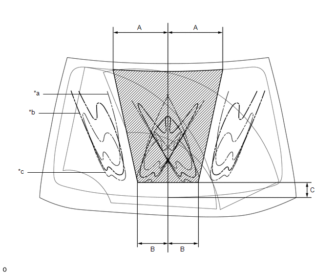
(a) Operate the washer nozzle sub-assemblies and check the position that the washer fluid contacts the windshield.
Standard:
Washer fluid contacts the windshield in the areas shown in the illustration.
|
*a |
Upper Limit |
*b |
Standard |
|
*c |
Lower Limit |
- |
- |
.png) |
Measurement |
- |
- |
Standard Measurement:
|
Area |
Measurement |
Area |
Measurement |
|---|---|---|---|
|
A |
341.0 mm (13.43 in.) |
B |
187.0 mm (7.36 in.) |
|
C |
82.5 mm (3.25 in.) |
- |
- |
HINT:
If the result is not as specified, replace the washer nozzle sub-assembly.
Removal
REMOVAL
CAUTION / NOTICE / HINT
PROCEDURE
1. REMOVE WASHER NOZZLE SUB-ASSEMBLY
HINT:
Use the same procedure as for the opposite side.
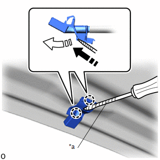
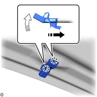
(a) Using a screwdriver with its tip wrapped in protective tape, disengage the claws as indicated by the arrows, shown in the illustration to separate the washer nozzle sub-assembly.
|
*a |
Protective Tape |
.png) |
Remove in this Direction (1) |
.png) |
Remove in this Direction (2) |
NOTICE:
Be careful not to damage the windshield glass.
|
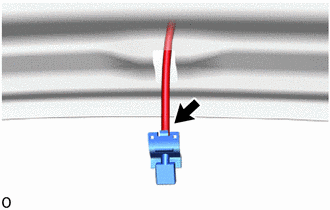
(b) Disconnect the washer hose to remove the washer nozzle sub-assembly. NOTICE: Washer nozzle sub-assemblies cannot be reused. |
|
Adjustment
ADJUSTMENT
PROCEDURE
1. REMOVE WASHER NOZZLE SUB-ASSEMBLY
Click here
.gif)
2. ADJUST WASHER NOZZLE SUB-ASSEMBLY
(a) Select a washer nozzle sub-assembly so that the position that the washer fluid hits the windshield will be within the standard area. Replace the washer nozzle sub-assembly with the selected one.
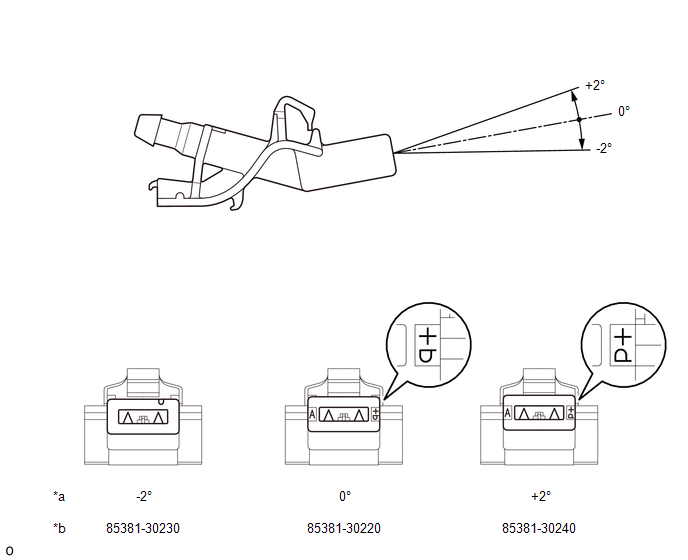
|
*a |
Washer Fluid Spray Angle |
*b |
Part Number |
3. INSTALL WASHER NOZZLE SUB-ASSEMBLY
Click here
Installation
INSTALLATION
CAUTION / NOTICE / HINT
PROCEDURE
1. INSTALL WASHER NOZZLE SUB-ASSEMBLY
HINT:
Use the same procedure as for the opposite side.
(a) Connect a new washer nozzle sub-assembly to the washer hose.
(b) Engage the claws as indicated by the arrows, shown in the illustration to install the washer nozzle sub-assembly.
.png) |
Install in this Direction (1) |
.png) |
Install in this Direction (2) |
2. INSPECT WASHER NOZZLE SUB-ASSEMBLY
Click here
.gif)
3. ADJUST WASHER NOZZLE SUB-ASSEMBLY
Click here
 Installation
INSTALLATION
PROCEDURE
1. INSTALL WINDSHIELD WASHER MOTOR AND PUMP ASSEMBLY
(a) Install the washer motor and pump assembly as shown in the illustration.
Install in this Direc ...
 Washer Nozzle(for Rear Side)
Components
COMPONENTS
ILLUSTRATION
*1
REAR WASHER NOZZLE
-
-
On-vehicle Inspection
ON-VEHICLE INSPECTION
PROCEDURE
1. INSPECT REAR WAS ...
Other materials:
Toyota CH-R Service Manual > Instrument Panel Safety Pad: Removal
REMOVAL
CAUTION / NOTICE / HINT
The necessary procedures (adjustment, calibration, initialization, or registration)
that must be performed after parts are removed, installed, or replaced during the
instrument panel safety pad sub-assembly removal/installation are shown below.
Necessary Proced ...
Toyota CH-R Service Manual > Airbag System: Short in Rear Pretensioner Squib RH Circuit (B1920/77-B1923/77)
DESCRIPTION
The rear pretensioner squib RH circuit consists of the airbag sensor assembly
and rear seat 3 point type outer belt assembly RH.
The airbag sensor assembly uses this circuit to deploy the pretensioner when
deployment conditions are met.
These DTCs are stored when a malfunction is ...
Toyota C-HR (AX20) 2023-2026 Owner's Manual
Toyota CH-R Owners Manual
- For safety and security
- Instrument cluster
- Operation of each component
- Driving
- Interior features
- Maintenance and care
- When trouble arises
- Vehicle specifications
- For owners
Toyota CH-R Service Manual
- Introduction
- Maintenance
- Audio / Video
- Cellular Communication
- Navigation / Multi Info Display
- Park Assist / Monitoring
- Brake (front)
- Brake (rear)
- Brake Control / Dynamic Control Systems
- Brake System (other)
- Parking Brake
- Axle And Differential
- Drive Shaft / Propeller Shaft
- K114 Cvt
- 3zr-fae Battery / Charging
- Networking
- Power Distribution
- Power Assist Systems
- Steering Column
- Steering Gear / Linkage
- Alignment / Handling Diagnosis
- Front Suspension
- Rear Suspension
- Tire / Wheel
- Tire Pressure Monitoring
- Door / Hatch
- Exterior Panels / Trim
- Horn
- Lighting (ext)
- Mirror (ext)
- Window / Glass
- Wiper / Washer
- Door Lock
- Heating / Air Conditioning
- Interior Panels / Trim
- Lighting (int)
- Meter / Gauge / Display
- Mirror (int)
- Power Outlets (int)
- Pre-collision
- Seat
- Seat Belt
- Supplemental Restraint Systems
- Theft Deterrent / Keyless Entry

0.0074