Toyota CH-R Service Manual: Installation
INSTALLATION
PROCEDURE
1. INSTALL REAR WIPER MOTOR ASSEMBLY
(a) Install the rear wiper motor assembly with the 3 bolts.
Torque:
5.5 N·m {56 kgf·cm, 49 in·lbf}
(b) Connect the connector.
2. INSTALL REAR WIPER MOTOR GROMMET
|
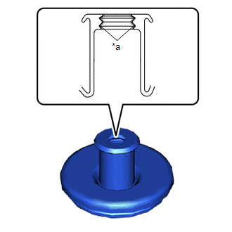
(a) Apply MP grease to the entire surface of the rear wiper motor grommet lip. HINT: Make sure that the hole does not get clogged with grease and the grooves on the lip are filled with grease. |
|
|
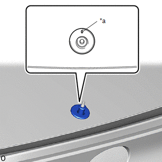
(b) Install the rear wiper motor grommet. HINT: Install the rear wiper motor grommet with its alignment mark facing up. |
|
3. INSTALL REAR WIPER ARM AND BLADE ASSEMBLY
|
(a) When reusing the rear wiper arm and blade assembly: (1) Clean the wiper arm serrations to remove any burrs, dirt, etc. NOTICE: Do not grind down the wiper arm serrations. |
|
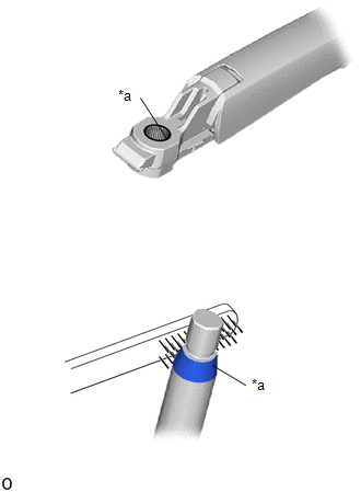
(b) When reusing the rear wiper motor assembly:
(1) Clean the wiper pivot serrations with a wire brush.
(c) Turn the ignition switch to ON.
(d) Operate the rear wiper motor assembly and stop it at the automatic stop position.
(e) Turn the ignition switch off.
|
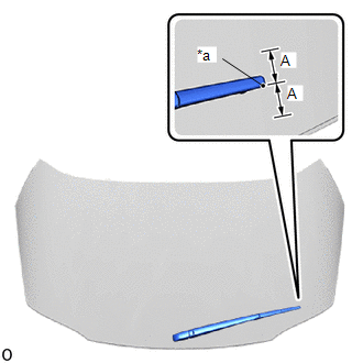
(f) Install the rear wiper arm and blade assembly with the nut to the position shown in the illustration. Torque: 5.5 N·m {56 kgf·cm, 49 in·lbf} HINT: Hold the rear wiper arm by hand while tightening the nut. Reference Measurement:
|
|
(g) Turn the ignition switch to ON.
(h) Operate the rear wiper while spraying washer fluid onto the back door glass. Make sure that the rear wiper functions properly and the wiper does not contact the vehicle body.
(i) Turn the ignition switch off.
(j) Lift the wiper arm twice after the wiper stops and check the wiper set position.
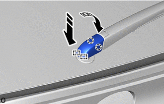
(k) Engage the claws and guides to close the rear wiper arm head cap as shown in the illustration.
.png) |
Remove in this Direction (1) |
.png) |
Remove in this Direction (2) |
|
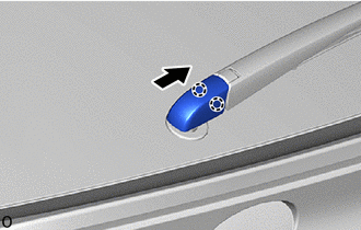
(l) Slide the rear wiper arm head cap to engage the 2 claws as shown in the illustration. |
|
4. INSTALL BACK DOOR TRIM PANEL ASSEMBLY
Click here
.gif)
5. INSTALL BACK DOOR SIDE GARNISH LH
Click here
6. INSTALL BACK DOOR SIDE GARNISH RH
HINT:
Use the same procedure as for the LH side.
7. INSTALL BACK DOOR TRIM UPPER PANEL ASSEMBLY
Click here
 Inspection
INSPECTION
PROCEDURE
1. INSPECT REAR WIPER MOTOR ASSEMBLY
*a
Component without harness connected
(Rear Wiper Motor Assembly)
(a) Check that the rear wiper motor ...
 Rear Wiper Rubber
Components
COMPONENTS
ILLUSTRATION
*1
REAR WIPER BLADE
*2
REAR WIPER RUBBER
*3
REAR WIPER RUBBER BACKING PLATE
...
Other materials:
Toyota CH-R Service Manual > Lighting System: Daytime Running Light Relay Circuit
DESCRIPTION
The main body ECU (multiplex network body ECU) controls the daytime running lights.
WIRING DIAGRAM
CAUTION / NOTICE / HINT
NOTICE:
Inspect the fuses for circuits related to this system before performing
the following procedure.
Before replacing the main body ECU (m ...
Toyota CH-R Service Manual > Spiral Cable: Inspection
INSPECTION
PROCEDURE
1. INSPECT SPIRAL CABLE SUB-ASSEMBLY
NOTICE:
Do not remove the steering sensor from the spiral cable sub-assembly
when inspecting the spiral cable sub-assembly.
Remove the steering sensor from the spiral cable sub-assembly only when
replacing the spiral c ...
Toyota C-HR (AX20) 2023-2026 Owner's Manual
Toyota CH-R Owners Manual
- For safety and security
- Instrument cluster
- Operation of each component
- Driving
- Interior features
- Maintenance and care
- When trouble arises
- Vehicle specifications
- For owners
Toyota CH-R Service Manual
- Introduction
- Maintenance
- Audio / Video
- Cellular Communication
- Navigation / Multi Info Display
- Park Assist / Monitoring
- Brake (front)
- Brake (rear)
- Brake Control / Dynamic Control Systems
- Brake System (other)
- Parking Brake
- Axle And Differential
- Drive Shaft / Propeller Shaft
- K114 Cvt
- 3zr-fae Battery / Charging
- Networking
- Power Distribution
- Power Assist Systems
- Steering Column
- Steering Gear / Linkage
- Alignment / Handling Diagnosis
- Front Suspension
- Rear Suspension
- Tire / Wheel
- Tire Pressure Monitoring
- Door / Hatch
- Exterior Panels / Trim
- Horn
- Lighting (ext)
- Mirror (ext)
- Window / Glass
- Wiper / Washer
- Door Lock
- Heating / Air Conditioning
- Interior Panels / Trim
- Lighting (int)
- Meter / Gauge / Display
- Mirror (int)
- Power Outlets (int)
- Pre-collision
- Seat
- Seat Belt
- Supplemental Restraint Systems
- Theft Deterrent / Keyless Entry

0.0078