Toyota CH-R Service Manual: Removal
REMOVAL
CAUTION / NOTICE / HINT
The necessary procedures (adjustment, calibration, initialization or registration) that must be performed after parts are removed and installed, or replaced during the power window regulator motor removal/installation are shown below.
Necessary Procedures After Parts Removed/Installed/Replaced|
Replaced Part or Performed Procedure |
Necessary Procedure |
Effect/Inoperative Function when Necessary Procedure not Performed |
Link |
|---|---|---|---|
|
Disconnect cable from negative (-) battery terminal |
Initialize back door lock |
Power door lock control system |
|
|
Memorize steering angle neutral point |
Lane departure alert system (w/ Steering Control) |
|
|
|
Pre-collision system |
|||
|
Initialize Power Window Control System |
|
|
HINT:
- Use the same procedure for the RH and LH sides.
- The procedure listed below is for the LH side.
PROCEDURE
1. PRECAUTION
NOTICE:
After turning the ignition switch off, waiting time may be required before disconnecting the cable from the negative (-) battery terminal. Therefore, make sure to read the disconnecting the cable from the negative (-) battery terminal notices before proceeding with work.
Click here
.gif)
2. DISCONNECT CABLE FROM NEGATIVE BATTERY TERMINAL
NOTICE:
When disconnecting the cable, some systems need to be initialized after the cable is reconnected.
Click here
3. REMOVE FRONT DOOR INSIDE HANDLE BEZEL PLUG
Click here
4. REMOVE MULTIPLEX NETWORK MASTER SWITCH ASSEMBLY WITH FRONT ARMREST BASE UPPER PANEL (for Driver Side)
Click here
5. REMOVE POWER WINDOW REGULATOR SWITCH ASSEMBLY WITH FRONT ARMREST BASE UPPER PANEL (for Front Passenger Side)
Click here
6. REMOVE FRONT DOOR TRIM BOARD SUB-ASSEMBLY
Click here
7. REMOVE FRONT DOOR GLASS INNER WEATHERSTRIP
Click here
8. REMOVE FRONT DOOR BELT SEAL
Click here
9. REMOVE FRONT DOOR SERVICE HOLE COVER
Click here
10. REMOVE FRONT DOOR GLASS SUB-ASSEMBLY
Click here
11. REMOVE NO. 2 FRONT DOOR SERVICE HOLE COVER
Click here
12. REMOVE FRONT DOOR WINDOW REGULATOR ASSEMBLY
Click here
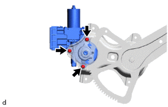
13. REMOVE POWER WINDOW REGULATOR MOTOR ASSEMBLY
|
(a) Using a T25 "TORX" socket wrench, remove the 3 screws and power window regulator motor assembly. |
|
 Inspection
INSPECTION
CAUTION / NOTICE / HINT
NOTICE:
Do not apply positive (+) battery voltage to any terminals, except terminal
2 (B), to avoid damaging the pulse sensor inside the motor.
Pe ...
 Installation
INSTALLATION
CAUTION / NOTICE / HINT
HINT:
Use the same procedure for the RH and LH sides.
The procedure listed below is for the LH side.
PROCEDURE
1. INSTALL POWER WINDOW REGUL ...
Other materials:
Toyota CH-R Owners Manual > Before driving: Dinghy towing
Your vehicle is not designed to be dinghy towed (with 4 wheels on
the ground) behind a motor home.
NOTICE■To avoid serious damage to your vehicle Do not tow
your vehicle with all four wheels on the ground.
...
Toyota CH-R Service Manual > 3zr-fae Battery: Components
COMPONENTS
ILLUSTRATION
*1
BATTERY
*2
NO. 2 BATTERY CLAMP
*3
POSITIVE BATTERY TERMINAL
*4
NEGATIVE BATTERY TERMINAL
*5
FUSIBLE LINK COVER
*6
BATTERY INS ...
Toyota C-HR (AX20) 2023-2026 Owner's Manual
Toyota CH-R Owners Manual
- For safety and security
- Instrument cluster
- Operation of each component
- Driving
- Interior features
- Maintenance and care
- When trouble arises
- Vehicle specifications
- For owners
Toyota CH-R Service Manual
- Introduction
- Maintenance
- Audio / Video
- Cellular Communication
- Navigation / Multi Info Display
- Park Assist / Monitoring
- Brake (front)
- Brake (rear)
- Brake Control / Dynamic Control Systems
- Brake System (other)
- Parking Brake
- Axle And Differential
- Drive Shaft / Propeller Shaft
- K114 Cvt
- 3zr-fae Battery / Charging
- Networking
- Power Distribution
- Power Assist Systems
- Steering Column
- Steering Gear / Linkage
- Alignment / Handling Diagnosis
- Front Suspension
- Rear Suspension
- Tire / Wheel
- Tire Pressure Monitoring
- Door / Hatch
- Exterior Panels / Trim
- Horn
- Lighting (ext)
- Mirror (ext)
- Window / Glass
- Wiper / Washer
- Door Lock
- Heating / Air Conditioning
- Interior Panels / Trim
- Lighting (int)
- Meter / Gauge / Display
- Mirror (int)
- Power Outlets (int)
- Pre-collision
- Seat
- Seat Belt
- Supplemental Restraint Systems
- Theft Deterrent / Keyless Entry

0.0092