Toyota CH-R Service Manual: Open in IG Circuit (B242E)
DESCRIPTION
This DTC is stored when a malfunction occurs in the headlight ECU sub-assembly LH IG power source circuit. The headlight ECU sub-assembly LH stores DTC B242E.
|
DTC No. |
Detection Item |
DTC Detection Condition |
Trouble Area |
Note |
|---|---|---|---|---|
|
B242E |
Open in IG Circuit |
Open in the headlight ECU sub-assembly LH IG power source circuit |
|
- |
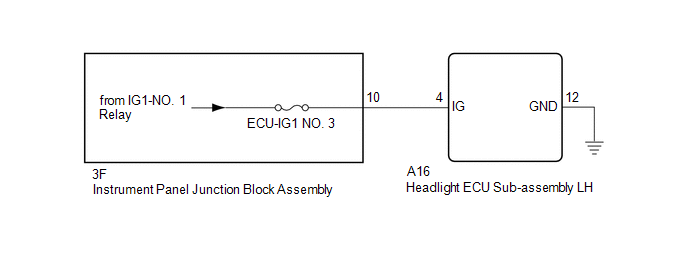
WIRING DIAGRAM
CAUTION / NOTICE / HINT
NOTICE:
- Inspect the fuses for circuits related to this system before performing the following procedure.
- If the headlight ECU sub-assembly LH has been replaced, it is necessary
to synchronize the vehicle information and initialize the headlight ECU
sub-assembly LH.
Click here
.gif)
PROCEDURE
|
1. |
CLEAR DTC |
(a) Clear the DTCs.
Click here
|
.gif)
|
2. |
CHECK FOR DTC |
(a) Turn the ignition switch to ON.
(b) Check for DTCs.
Click here
OK:
DTC B242E is not output.
| OK | .gif) |
USE SIMULATION METHOD TO CHECK
|
|
|
3. |
CHECK HARNESS AND CONNECTOR (HEADLIGHT ECU SUB-ASSEMBLY LH - POWER SOURCE AND BODY GROUND) |
(a) Disconnect the A16 headlight ECU sub-assembly LH connector.
(b) Measure the voltage according to the value(s) in the table below.
Standard Voltage:
|
Tester Connection |
Switch Condition |
Specified Condition |
|---|---|---|
|
A16-4 (IG) - Body ground |
Ignition switch off |
Below 1 V |
|
A16-4 (IG) - Body ground |
Ignition switch ON |
11 to 14 V |
(c) Measure the resistance according to the value(s) in the table below.
Standard Resistance:
|
Tester Connection |
Condition |
Specified Condition |
|---|---|---|
|
A16-12 (GND) - Body ground |
Always |
Below 1 Ω |
| OK | |
REPLACE HEADLIGHT ECU SUB-ASSEMBLY LH |
| NG | |
REPAIR OR REPLACE HARNESS OR CONNECTOR |
 Right Headlight ECU Malfunction (B242C,B242D)
DESCRIPTION
These DTCs are stored if the headlight ECU sub-assembly LH or RH detects an internal
malfunction. The headlight ECU sub-assembly LH stores DTC B242C or B242D.
DTC No.
...
 Vehicle Specifications have not been Stored (B2451)
DESCRIPTION
This DTC is output if the vehicle variation information is not written to the
headlight ECU sub-assembly LH.
The headlight ECU sub-assembly LH outputs DTC B2451.
DTC No.
...
Other materials:
Toyota CH-R Service Manual > Seat Belt Warning System(w/o Occupant Classification System): On-vehicle Inspection
ON-VEHICLE INSPECTION
PROCEDURE
1. INSPECT DRIVER SEAT BELT WARNING SYSTEM
HINT:
The seat belt warning light on the combination meter assembly is used for both
the driver seat and front passenger seat.
(a) Turn the ignition switch to ON.
(b) When the driver seat belt is not fastened, check t ...
Toyota CH-R Owners Manual > If you have a flat tire: Location of the spare tire, jack and tools
Towing eyelet
Wheel nut wrench
Jack
Jack handle
Spare tire
WARNING■Using the tire jack Observe the
following precautions.
Improper use of the tire jack may cause the vehicle to suddenly fall off
the jack, leading to death or serious injury.
Do not use the tire ja ...
Toyota C-HR (AX20) 2023-2026 Owner's Manual
Toyota CH-R Owners Manual
- For safety and security
- Instrument cluster
- Operation of each component
- Driving
- Interior features
- Maintenance and care
- When trouble arises
- Vehicle specifications
- For owners
Toyota CH-R Service Manual
- Introduction
- Maintenance
- Audio / Video
- Cellular Communication
- Navigation / Multi Info Display
- Park Assist / Monitoring
- Brake (front)
- Brake (rear)
- Brake Control / Dynamic Control Systems
- Brake System (other)
- Parking Brake
- Axle And Differential
- Drive Shaft / Propeller Shaft
- K114 Cvt
- 3zr-fae Battery / Charging
- Networking
- Power Distribution
- Power Assist Systems
- Steering Column
- Steering Gear / Linkage
- Alignment / Handling Diagnosis
- Front Suspension
- Rear Suspension
- Tire / Wheel
- Tire Pressure Monitoring
- Door / Hatch
- Exterior Panels / Trim
- Horn
- Lighting (ext)
- Mirror (ext)
- Window / Glass
- Wiper / Washer
- Door Lock
- Heating / Air Conditioning
- Interior Panels / Trim
- Lighting (int)
- Meter / Gauge / Display
- Mirror (int)
- Power Outlets (int)
- Pre-collision
- Seat
- Seat Belt
- Supplemental Restraint Systems
- Theft Deterrent / Keyless Entry

0.0086