Toyota CH-R Service Manual: Terminals Of Ecu
TERMINALS OF ECU
|
*A |
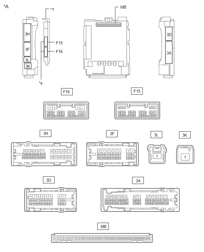
Main Body ECU (Multiplex Network Body ECU) with 2 Connectors |
- |
- |
|
*1 |
Main Body ECU (Multiplex Network Body ECU) with 2 Connectors |
- |
- |
|
*a |
2 Connectors |
- |
- |
CHECK INSTRUMENT PANEL JUNCTION BLOCK ASSEMBLY AND MAIN BODY ECU (MULTIPLEX NETWORK BODY ECU)
|
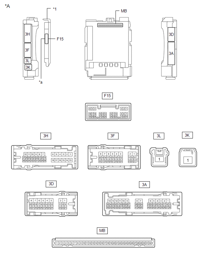
*A |
Main Body ECU (Multiplex Network Body ECU) with 1 Connector |
- |
- |
|
*1 |
Main Body ECU (Multiplex Network Body ECU) |
- |
- |
|
*a |
Main Body ECU (Multiplex Network Body ECU) |
- |
- |
(a) Disconnect the instrument panel junction block assembly and main body ECU (multiplex network body ECU) connectors.
(b) Measure the voltage on the wire harness side connector according to the value(s) in the table below.
|
Terminal No. (Symbol) |
Wiring Color |
Terminal Description |
Condition |
Specified Condition |
|---|---|---|---|---|
|
3F-1 - Body ground |
W - Body ground |
Battery power supply |
Always |
11 to 14 V |
|
3K-1 - Body ground |
B-R - Body ground |
Battery power supply |
Always |
11 to 14 V |
If the result is not as specified, there may be a malfunction in the wire harness.
(c) Measure the resistance on the wire harness side connector according to the value(s) in the table below.
|
Terminal No. (Symbol) |
Wiring Color |
Terminal Description |
Condition |
Specified Condition |
|---|---|---|---|---|
|
3D-3 - Body ground |
W-B - Body ground |
Ground |
Always |
Below 1 Ω |
If the result is not as specified, there may be a malfunction in the wire harness.
(d) Reconnect the instrument panel junction block assembly and main body ECU (multiplex network body ECU) connectors.
(e) Measure the voltage and check for pulses according to the value(s) in the table below.
|
Terminal No. (Symbol) |
Wiring Color |
Terminal Description |
Condition |
Specified Condition |
|---|---|---|---|---|
|
3H-30 - Body ground |
G - Body ground |
Taillights and license plate lights drive output |
Light control switch in tail or head position |
11 to 14 V |
|
Light control switch off*1 |
Below 1 V |
|||
|
3A-52 - Body ground*2 |
L - Body ground |
Front fog light drive output |
Light control switch in tail or head position, fog light switch in front position |
Below 1 V |
|
Light control switch in tail or head position, fog light switch off |
11 to 14 V |
|||
|
3F-31 - Body ground |
G - Body ground |
H-LP LH relay drive output |
Ignition switch off |
11 to 14 V |
|
Ignition switch ON |
Below 1 V |
|||
|
F15-1 (DIM) - Body ground |
Y - Body ground |
H-LP RH relay drive output |
Ignition switch off |
11 to 14 V |
|
Ignition switch ON |
Below 1 V |
|||
|
F15-8 (A) - Body ground |
W - Body ground |
Light control switch AUTO position signal input |
Light control switch in AUTO position |
Below 1 V |
|
Light control switch not in AUTO position |
Pulse generation |
|||
|
F15-10 (HF) - Body ground |
LG - Body ground |
Dimmer switch high flash position signal input |
Dimmer switch in high flash position |
Below 1 V |
|
Dimmer switch not in high flash position |
Pulse generation |
|||
|
F15-12 (HEAD) - Body ground |
L - Body ground |
Light control switch head position input |
Light control switch in head position |
Below 1 V |
|
Light control switch not in head position |
Pulse generation |
|||
|
F15-19 (CLTB) - F15-21 (CLTE) |
G - V |
Automatic light control sensor power supply output |
Ignition switch off |
Below 1 V |
|
Ignition switch ON |
11 to 14 V |
|||
|
F15-20 (CLTS) - Body ground |
BE - Body ground |
Automatic light control sensor signal input |
Ignition switch off |
Below 1 V |
|
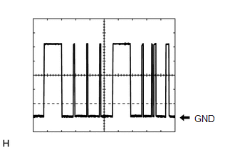
Automatic light control system operating |
Communication waveform generation (See waveform 1) |
|||
|
F15-22 (TAIL) - Body ground |
Y - Body ground |
Light control switch tail position signal input |
Light control switch in tail or head position |
Below 1 V |
|
Light control switch not in tail or head position |
Pulse generation |
|||
|
F15-24 (HU) - Body ground |
GR - Body ground |
Dimmer switch high position signal input |
Dimmer switch in high position |
Below 1 V |
|
Dimmer switch not in high position |
Pulse generation |
|||
|
F15-26 (FFOG) - Body ground*2 |
R - Body ground |
Fog light switch front position input |
Fog light switch in front position |
Below 1 V |
|
Fog light switch off |
Pulse generation |
|||
|
F16-4 (MILE) - Body ground*3 |
R - Body ground |
Door mirror foot lights drive output |
Door mirror foot light illuminates |
11 to 14 V |
|
Door mirror foot light off |
Below 3 V |
- *1: If the light switch has no OFF position, set the light switch to "Auto" with the Lo beam turned off. If the Lo beam is illuminated, shine a fluorescent light or other light source onto the light sensor to enter daytime mode.
- *2: w/ Fog Light
- *3: w/ Door Mirror Foot Light
If the result is not as specified, the main body ECU (multiplex network body ECU) or instrument panel junction block assembly may be malfunctioning.
(1) Waveform 1
|
Item |
Content |
|---|---|
|
Tool setting |
2 V/DIV., 10 ms./DIV. |
HINT:
The communication waveform changes according to the surrounding brightness.
CHECK HEADLIGHT ECU SUB-ASSEMBLY LH (for LED Headlight)
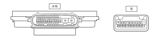
(a) Disconnect the A16 headlight ECU sub-assembly LH connector.
(b) Measure the resistance and voltage on the wire harness side connector according to the value(s) in the table below.
|
Terminal No. (Symbol) |
Wiring Color |
Terminal Description |
Condition |
Specified Condition |
|---|---|---|---|---|
|
A16-4 (IG) - Body ground |
V - Body ground |
Ignition power supply |
Ignition switch off |
Below 1 V |
|
Ignition switch ON |
11 to 14 V |
|||
|
A16-13 (ECUB) - Body ground |
L - Body ground |
Battery power supply |
Light control switch off* |
Below 1 V |
|
Light control switch in tail or head position |
11 to 14 V |
|||
|
A16-12 (GND) - Body ground |
W-B - Body ground |
Ground |
Always |
Below 1 Ω |
- *: If the light switch has no OFF position, set the light switch to "Auto" with the Lo beam turned off. If the Lo beam is illuminated, shine a fluorescent light or other light source onto the light sensor to enter daytime mode.
(c) Reconnect the A16 headlight ECU sub-assembly LH connector.
HINT:
- Since the A16 headlight ECU sub-assembly LH connector is a waterproof type connector, the voltage cannot be measured and pulses cannot be checked for directly. The values listed are for reference only.
- Since the B headlight ECU sub-assembly LH connector is connected inside the headlight assembly, the voltage cannot be measured and pulses cannot be checked for directly. The values listed are for reference only.
(d) Measure the voltage and check of pulses according to the value(s) in the table below.
|
Terminal No. (Symbol) |
Wiring Color |
Terminal Description |
Condition |
Specified Condition |
|---|---|---|---|---|
|
A16-11 (TNS) - Body ground |
W - Body ground |
Left turn signal light signal input |
Ignition switch ON, left turn signal light off |
Below 1 V |
|
Ignition switch ON, left turn signal light blinking |
11 to 14 V ←→ Below 1 V |
|||
|
A16-16 (SBR) - A16-15 (SGR) |
B - BE |
Rear height control sensor sub-assembly LH power supply |
Ignition switch ON |
4.75 to 5.25 V |
|
A16-17 (SHRL) - A16-15 (SGR) |
W - BE |
Rear height control sensor sub-assembly LH signal input |
Ignition switch ON, vehicle unloaded, vehicle stopped |
Approximately 2.5 V (value decreases as the front of the vehicle is raised) |
|
A16-20 (LINL) - Body ground |
P - Body ground |
LIN communication line |
Ignition switch off |
Below 1 V |
|
Ignition switch ON |
Pulse generation |
|||
|
B-20 (DRL+) - B-11 (DRL-) |
- |
High beam headlights drive output |
High beam headlights off |
Below 1 V |
|
High beam headlights on |
11 to 14 V |
|||
|
B-4 (LOLED2) - B-3 (LOLED0) |
- |
Low beam headlights/high beam headlights drive output |
Low beam headlights and high beam headlights off |
Below 1 V |
|
Low beam headlights or high beam headlights on |
11.2 to 17.7 V |
|||
|
B-7 (ACTBI) - B-17 (ACTGI) |
- |
Headlight leveling motor power source |
Ignition switch off |
Below 1 V |
|
Ignition switch ON |
11 to 14 V |
|||
|
B-8 (ACTSI) - B-17 (ACTGI) |
- |
Headlight leveling motor signal output |
Ignition switch ON, low beam headlights on, vehicle height not changed |
Below 1 V |
|
Ignition switch ON, low beam headlights on, vehicle height changed and maintained for more than 3 seconds |
1.0 to 14 V |
|||
|
B-9 (TURN+) - B-13 (TURN-) |
- |
Left turn signal light signal output |
Ignition switch ON, left turn signal light off |
Below 1 V |
|
Ignition switch ON, left turn signal light blinking |
11 to 14 V ←→ Below 1 V |
|||
|
B-16 (PWM1) - B-1 (HI-) |
- |
Daytime running lights/clearance lights control signal output |
Daytime running lights and clearance lights off |
Below 1 V |
|
Daytime running lights or clearance lights on |
Pulse generation |
|||
|
B-10 (HI+) - B-1 (HI-) |
- |
Daytime running lights/clearance lights power source |
Daytime running lights and clearance lights off |
Below 1 V |
|
Daytime running lights or clearance lights on |
11 to 14 V |
CHECK HEADLIGHT ECU SUB-ASSEMBLY RH (for LED Headlight)

(a) Disconnect the A17 headlight ECU sub-assembly RH connector.
(b) Measure the resistance and voltage on the wire harness side connector according to the value(s) in the table below.
|
Terminal No. (Symbol) |
Wiring Color |
Terminal Description |
Condition |
Specified Condition |
|---|---|---|---|---|
|
A17-4 (IG) - Body ground |
V - Body ground |
Ignition power supply |
Ignition switch off |
Below 1 V |
|
Ignition switch ON |
11 to 14 V |
|||
|
A17-13 (ECUB) - Body ground |
L - Body ground |
Battery power supply |
Light control switch off* |
Below 1 V |
|
Light control switch in tail or head position |
11 to 14 V |
|||
|
A17-12 (GND) - Body ground |
W-B - Body ground |
Ground |
Always |
Below 1 Ω |
- *: If the light switch has no OFF position, set the light switch to "Auto" with the Lo beam turned off. If the Lo beam is illuminated, shine a fluorescent light or other light source onto the light sensor to enter daytime mode.
(c) Reconnect the A17 headlight ECU sub-assembly RH connector.
HINT:
- Since the A17 headlight ECU sub-assembly RH connector is a waterproof type connector, the voltage cannot be measured and pulses cannot be checked for directly. The values listed are for reference only.
- Since the B headlight ECU sub-assembly RH connector is connected inside the headlight assembly, the voltage cannot be measured and pulses cannot be checked for directly. The values listed are for reference only.
(d) Measure the voltage and check of pulses according to the value(s) in the table below.
|
Terminal No. (Symbol) |
Wiring Color |
Terminal Description |
Condition |
Specified Condition |
|---|---|---|---|---|
|
A17-11 (TNS) - Body ground |
B - Body ground |
Right turn signal light signal input |
Ignition switch ON, right turn signal light off |
Below 1 V |
|
Ignition switch ON, right turn signal light blinking |
11 to 14 V ←→ Below 1 V |
|||
|
A17-20 (LINL) - Body ground |
P - Body ground |
LIN communication line |
Ignition switch off |
Below 1 V |
|
Ignition switch ON |
Pulse generation |
|||
|
B-20 (DRL+) - B-11 (DRL-) |
- |
High beam headlights drive output |
High beam headlights off |
Below 1 V |
|
High beam headlights on |
11 to 14 V |
|||
|
B-4 (LOLED2) - B-3 (LOLED0) |
- |
Low beam headlights/high beam headlights drive output |
Low beam headlights and high beam headlights off |
Below 1 V |
|
Low beam headlights or high beam headlights on |
11.2 to 17.7 V |
|||
|
B-7 (ACTBI) - B-17 (ACTGI) |
- |
Headlight leveling motor power source |
Ignition switch off |
Below 1 V |
|
Ignition switch ON |
11 to 14 V |
|||
|
B-8 (ACTSI) - B-17 (ACTGI) |
- |
Headlight leveling motor signal output |
Ignition switch ON, low beam headlights on, vehicle height not changed |
Below 1 V |
|
Ignition switch ON, low beam headlights on, vehicle height changed and maintained for more than 3 seconds |
1.0 to 14 V |
|||
|
B-9 (TURN+) - B-13 (TURN-) |
- |
Right turn signal light signal output |
Ignition switch ON, right turn signal light off |
Below 1 V |
|
Ignition switch ON, right turn signal light blinking |
11 to 14 V ←→ Below 1 V |
|||
|
B-16 (PWM1) - B-1 (HI-) |
- |
Daytime running lights/clearance lights control signal output |
Daytime running lights and clearance lights off |
Below 1 V |
|
Daytime running lights or clearance lights on |
Pulse generation |
|||
|
B-10 (HI+) - B-1 (HI-) |
- |
Daytime running lights/clearance lights power source |
Daytime running lights and clearance lights off |
Below 1 V |
|
Daytime running lights or clearance lights on |
11 to 14 V |
CHECK COMBINATION METER ASSEMBLY
Click here
.gif)
 Problem Symptoms Table
PROBLEM SYMPTOMS TABLE
NOTICE:
Before replacing the main body ECU (multiplex network body ECU), refer
to Registration.*1
Click here
If the headlight ECU sub-assembly LH ...
 Diagnosis System
DIAGNOSIS SYSTEM
DESCRIPTION
(a) Lighting system data and Diagnostic Trouble Codes (DTCs) can be read from
the Data Link Connector 3 (DLC3) of the vehicle. When the system seems to be malfunctioni ...
Other materials:
Toyota CH-R Service Manual > Meter / Gauge System: Fuel Receiver Gauge Display Malfunction
DESCRIPTION
OPERATION
The combination meter assembly uses the fuel injection volume signal from the
ECM, fuel sender gauge assembly to detect the amount of fuel remaining in the fuel
tank assembly. Each gauge assembly has a variable resistor whose resistance changes
according to the amount o ...
Toyota CH-R Service Manual > Air Conditioning System(for Automatic Air Conditioning System With Top-mounted
Air Conditioner Pressure Sensor): Compressor Solenoid Circuit (B1451)
DESCRIPTION
In this circuit, the compressor with pulley assembly (compressor solenoid) receives
a refrigerant compression demand signal from the air conditioning amplifier assembly.
Based on this signal, the compressor with pulley assembly (compressor solenoid)
changes the amount of compressor ...
Toyota C-HR (AX20) 2023-2026 Owner's Manual
Toyota CH-R Owners Manual
- For safety and security
- Instrument cluster
- Operation of each component
- Driving
- Interior features
- Maintenance and care
- When trouble arises
- Vehicle specifications
- For owners
Toyota CH-R Service Manual
- Introduction
- Maintenance
- Audio / Video
- Cellular Communication
- Navigation / Multi Info Display
- Park Assist / Monitoring
- Brake (front)
- Brake (rear)
- Brake Control / Dynamic Control Systems
- Brake System (other)
- Parking Brake
- Axle And Differential
- Drive Shaft / Propeller Shaft
- K114 Cvt
- 3zr-fae Battery / Charging
- Networking
- Power Distribution
- Power Assist Systems
- Steering Column
- Steering Gear / Linkage
- Alignment / Handling Diagnosis
- Front Suspension
- Rear Suspension
- Tire / Wheel
- Tire Pressure Monitoring
- Door / Hatch
- Exterior Panels / Trim
- Horn
- Lighting (ext)
- Mirror (ext)
- Window / Glass
- Wiper / Washer
- Door Lock
- Heating / Air Conditioning
- Interior Panels / Trim
- Lighting (int)
- Meter / Gauge / Display
- Mirror (int)
- Power Outlets (int)
- Pre-collision
- Seat
- Seat Belt
- Supplemental Restraint Systems
- Theft Deterrent / Keyless Entry

0.008