Toyota CH-R Service Manual: Inspection
INSPECTION
PROCEDURE
1. INSPECT REAR HEIGHT CONTROL SENSOR SUB-ASSEMBLY LH
(a) Preparation for check
(1) Confirm the standard, high and low positions of the link that will be used in the following inspection.
- The standard position is 58° from the maximum link angle (high) and 51° from the maximum link angle (low).
- The high position (+33.85°) is 24.15° from the maximum link angle (high).
- The low position (-33.85°) is 17.15° from the maximum link angle (low).
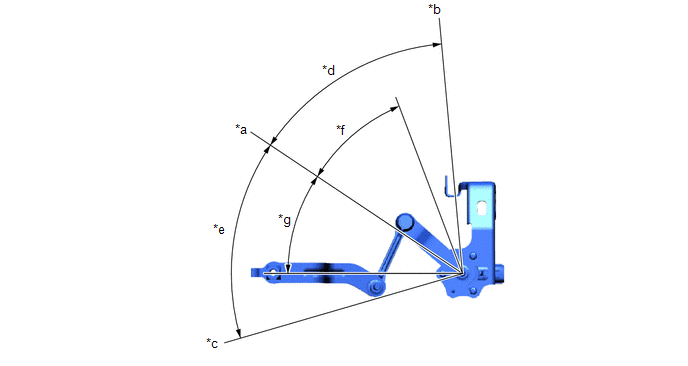
|
*a |
Standard Position |
*b |
Maximum Link Angle (Low) |
|
*c |
Maximum Link Angle (High) |
*d |
51° |
|
*e |
58° |
*f |
-33.85° |
|
*g |
+33.85° |
- |
- |
(2) Connect 3 dry cell batteries (1.5 V) in series.
NOTICE:
Do not use rechargeable batteries as they may not output a voltage of 1.5 V.
(3) Connect a positive (+) lead from the batteries to terminal 3 (SHB) and a negative (-) lead to terminal 1 (SHG).
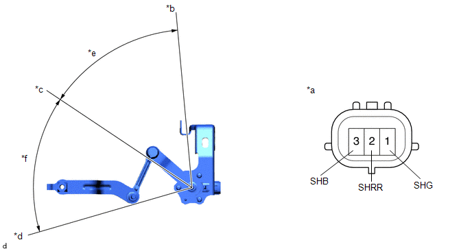
|
*a |
Component without harness connected (Rear Height Control Sensor Sub-assembly LH) |
*b |
Low |
|
*c |
Standard Position |
*d |
High |
|
*e |
-33.85° |
*f |
+33.85° |
(4) Measure the voltage between terminals 2 (SHRR) and 1 (SHG) while slowly moving the link up and down.
Standard Voltage:
|
Tester Connection |
Condition |
Specified Condition |
|---|---|---|
|
1 (SHG) - 2 (SHRR) |
+33.85° (High) |
4.15 V |
|
1 (SHG) - 2 (SHRR) |
0° (Standard position) |
2.5 V |
|
1 (SHG) - 2 (SHRR) |
-33.85° (Low) |
1.04 V |
If the result is not as specified, replace the rear height control sensor sub-assembly LH.
 Removal
REMOVAL
CAUTION / NOTICE / HINT
The necessary procedures (adjustment, calibration, initialization or registration)
that must be performed after parts are removed and installed, or replaced during ...
 Installation
INSTALLATION
PROCEDURE
1. INSTALL REAR HEIGHT CONTROL SENSOR SUB-ASSEMBLY LH
(a) Engage the hook.
*a
...
Other materials:
Toyota CH-R Service Manual > Audio And Visual System(for Radio And Display Type): Certification ECU Vehicle Information Reading/Writing Process Malfunction (B15F7)
DESCRIPTION
This DTC is stored when items controlled by the certification ECU (smart key
ECU assembly) cannot be customized via the audio and visual system vehicle customization
screen.
HINT:
The certification ECU (smart key ECU assembly) controls the smart key system
related items that are ...
Toyota CH-R Owners Manual > Do-it-yourself maintenance: Tires
Replace or rotate tires in accordance with maintenance schedules
and treadwear.
Checking tires
Check if the treadwear indicators are showing on the tires. Also check the tires
for uneven wear, such as excessive wear on one side of the tread.
Check the spare tire condition and pressure if not ...
Toyota C-HR (AX20) 2023-2026 Owner's Manual
Toyota CH-R Owners Manual
- For safety and security
- Instrument cluster
- Operation of each component
- Driving
- Interior features
- Maintenance and care
- When trouble arises
- Vehicle specifications
- For owners
Toyota CH-R Service Manual
- Introduction
- Maintenance
- Audio / Video
- Cellular Communication
- Navigation / Multi Info Display
- Park Assist / Monitoring
- Brake (front)
- Brake (rear)
- Brake Control / Dynamic Control Systems
- Brake System (other)
- Parking Brake
- Axle And Differential
- Drive Shaft / Propeller Shaft
- K114 Cvt
- 3zr-fae Battery / Charging
- Networking
- Power Distribution
- Power Assist Systems
- Steering Column
- Steering Gear / Linkage
- Alignment / Handling Diagnosis
- Front Suspension
- Rear Suspension
- Tire / Wheel
- Tire Pressure Monitoring
- Door / Hatch
- Exterior Panels / Trim
- Horn
- Lighting (ext)
- Mirror (ext)
- Window / Glass
- Wiper / Washer
- Door Lock
- Heating / Air Conditioning
- Interior Panels / Trim
- Lighting (int)
- Meter / Gauge / Display
- Mirror (int)
- Power Outlets (int)
- Pre-collision
- Seat
- Seat Belt
- Supplemental Restraint Systems
- Theft Deterrent / Keyless Entry

0.0097