Toyota CH-R Service Manual: Tire Pressure Monitor Receiver Communication Stop (B1247)
DESCRIPTION
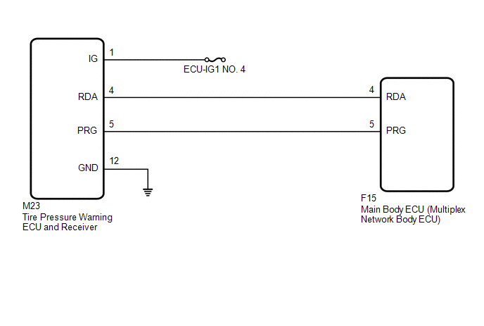
The main body ECU (multiplex network body ECU) and tire pressure warning ECU and receiver are connected using 2 direct lines that they use to communicate with each other.
|
DTC No. |
Detection Item |
DTC Detection Condition |
Trouble Area |
Note |
|---|---|---|---|---|
|
B1247 |
Tire Pressure Monitor Receiver Communication Stop |
In diagnostic mode, an applicable RDA signal cannot be received within 10 seconds after a PRG signal is sent from the main body ECU (multiplex network body ECU). |
|
This DTC is for main body ECU (multiplex network body ECU) |
WIRING DIAGRAM
CAUTION / NOTICE / HINT
NOTICE:
- When replacing the tire pressure warning ECU and receiver, read the
IDs stored in the old ECU using the Techstream and write them down before
removal.
Click here
.gif)
- It is necessary to perform initialization
after registration
of the transmitter IDs into the tire pressure warning ECU and receiver after
the ECU has been replaced.
- If the main body ECU (multiplex network body ECU) is replaced, refer
to Registration.*
*: w/ Smart Key System
Click here
HINT:
Inspect the fuses for circuits related to this system before performing the following inspection procedure.
PROCEDURE
|
1. |
CHECK HARNESS AND CONNECTOR (MAIN BODY ECU (MULTIPLEX NETWORK BODY ECU) - TIRE PRESSURE WARNING ECU AND RECEIVER) |
(a) Turn the ignition switch off.
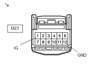
(b) Disconnect the M23 tire pressure warning ECU and receiver connector.
(c) Disconnect the F15 main body ECU (multiplex network body ECU) connector.
(d) Measure the resistance according to the value(s) in the table below.
Standard Resistance:
|
Tester Connection |
Condition |
Specified Condition |
|---|---|---|
|
M23-4 (RDA) - F15-4 (RDA) |
Always |
Below 1 Ω |
|
M23-4 (RDA) or F15-4 (RDA) - Body ground |
Always |
10 kΩ or higher |
| NG | .gif) |
REPAIR OR REPLACE HARNESS OR CONNECTOR |
|
.gif)
|
2. |
CHECK HARNESS AND CONNECTOR (POWER SOURCE OF TIRE PRESSURE WARNING ECU AND RECEIVER) |
|
(a) Measure the resistance according to the value(s) in the table below. Standard Resistance:
|
|
(b) Measure the voltage according to the value(s) in the table below.
Standard Voltage:
|
Tester Connection |
Condition |
Specified Condition |
|---|---|---|
|
M23-1 (IG) - Body ground |
Ignition switch to ON |
10 to 16 V |
| NG | |
REPAIR OR REPLACE HARNESS OR CONNECTOR |
|
|
3. |
REPLACE TIRE PRESSURE WARNING ECU AND RECEIVER |
(a) Replace the tire pressure warning ECU and receiver.
Click here
|
|
4. |
CHECK DTC OUTPUT |
(a) Clear the DTCs.
Click here
(b) Turn the ignition switch off.
(c) Turn the ignition switch to ON.
(d) Check for DTCs.
Click here
OK:
DTC B1247 is not output.
| OK | |
END |
| NG | |
REPLACE MAIN BODY ECU (MULTIPLEX NETWORK BODY ECU)
|
 Receiver Error (C2176/76)
DESCRIPTION
The signals are transmitted to the tire pressure warning ECU and receiver in
the vehicle as radio waves.
DTC No.
Detection Item
DTC Detection Condition ...
 Transmitter ID1 Operation Stop (C2111/11-C2115/15)
DESCRIPTION
The tire pressure warning valve and transmitters that are installed in the tire
and wheel assemblies measure the tire pressures. The measured values are transmitted
to the tire pressu ...
Other materials:
Toyota CH-R Service Manual > Steering Pad Switch: Inspection
INSPECTION
PROCEDURE
1. INSPECT STEERING PAD SWITCH ASSEMBLY
(a) Measure the resistance according to the value(s) in the table below.
*A
w/ Lane Departure Alert System
*B
w/ Voice Switch
*C
w/ Microphone
-
...
Toyota CH-R Service Manual > Pre-collision System: Steering Angle Sensor (C1A47)
DESCRIPTION
The millimeter wave radar sensor assembly receives steering angle information
from the steering angle sensor (spiral cable with sensor sub-assembly). If the millimeter
wave radar sensor assembly detects a steering angle sensor (spiral cable with sensor
sub-assembly) malfunction, D ...
Toyota C-HR (AX20) 2023-2026 Owner's Manual
Toyota CH-R Owners Manual
- For safety and security
- Instrument cluster
- Operation of each component
- Driving
- Interior features
- Maintenance and care
- When trouble arises
- Vehicle specifications
- For owners
Toyota CH-R Service Manual
- Introduction
- Maintenance
- Audio / Video
- Cellular Communication
- Navigation / Multi Info Display
- Park Assist / Monitoring
- Brake (front)
- Brake (rear)
- Brake Control / Dynamic Control Systems
- Brake System (other)
- Parking Brake
- Axle And Differential
- Drive Shaft / Propeller Shaft
- K114 Cvt
- 3zr-fae Battery / Charging
- Networking
- Power Distribution
- Power Assist Systems
- Steering Column
- Steering Gear / Linkage
- Alignment / Handling Diagnosis
- Front Suspension
- Rear Suspension
- Tire / Wheel
- Tire Pressure Monitoring
- Door / Hatch
- Exterior Panels / Trim
- Horn
- Lighting (ext)
- Mirror (ext)
- Window / Glass
- Wiper / Washer
- Door Lock
- Heating / Air Conditioning
- Interior Panels / Trim
- Lighting (int)
- Meter / Gauge / Display
- Mirror (int)
- Power Outlets (int)
- Pre-collision
- Seat
- Seat Belt
- Supplemental Restraint Systems
- Theft Deterrent / Keyless Entry

0.0069