Toyota CH-R Service Manual: Removal
REMOVAL
CAUTION / NOTICE / HINT
The necessary procedures (adjustment, calibration, initialization or registration) that must be performed after parts are removed and installed, or replaced during the height control sensor sub-assembly removal/ installation are shown below.
Necessary Procedures After Parts Removed/Installed/Replaced|
Replaced Part or Performed Procedure |
Necessary Procedure |
Effect/Inoperative Function when Necessary Procedure not Performed |
Link |
|---|---|---|---|
|
Rear height control sensor sub-assembly LH |
Initialize headlight ECU sub-assembly LH |
Automatic headlight beam level control system |
|
PROCEDURE
1. REMOVE REAR WHEEL (for LH Side)
Click here
.gif)
2. REMOVE REAR HEIGHT CONTROL SENSOR SUB-ASSEMBLY LH
|
(a) Disconnect the connector. |
|
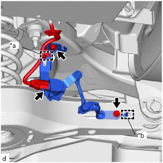
(b) Disengage the clamp.
(c) Remove the 2 bolts.
(d) Disengage the hook to remove the rear height control sensor sub-assembly LH.
NOTICE:
If the rear height control sensor sub-assembly LH has been struck or dropped, replace it with a new one.
 Components
COMPONENTS
ILLUSTRATION
*1
REAR HEIGHT CONTROL SENSOR SUB-ASSEMBLY LH
-
-
N*m (kgf*cm, ft.*lbf): Specified torque
- ...
 Inspection
INSPECTION
PROCEDURE
1. INSPECT REAR HEIGHT CONTROL SENSOR SUB-ASSEMBLY LH
(a) Preparation for check
(1) Confirm the standard, high and low positions of the link that will be used
in the followi ...
Other materials:
Toyota CH-R Service Manual > Immobiliser System(w/o Smart Key System): Diagnosis System
DIAGNOSIS SYSTEM
DESCRIPTION
(a) The transponder key ECU assembly controls the immobiliser system. Immobiliser
system data and Diagnostic Trouble Codes (DTCs) can be read through the vehicle
Data Link Connector 3 (DLC3).
CHECK DLC3
(a) Check the DLC3.
Click here
INSPECT BATTERY VOLTAGE
...
Toyota CH-R Service Manual > Pre-collision System: Brake System Malfunction (C1A50)
DESCRIPTION
When the pre-collision system is operating, the millimeter wave radar sensor
assembly sends brake control signals to the skid control ECU (brake actuator assembly).
When the millimeter wave radar sensor assembly receives a VSC system malfunction
signal from the skid control ECU (br ...
Toyota C-HR (AX20) 2023-2026 Owner's Manual
Toyota CH-R Owners Manual
- For safety and security
- Instrument cluster
- Operation of each component
- Driving
- Interior features
- Maintenance and care
- When trouble arises
- Vehicle specifications
- For owners
Toyota CH-R Service Manual
- Introduction
- Maintenance
- Audio / Video
- Cellular Communication
- Navigation / Multi Info Display
- Park Assist / Monitoring
- Brake (front)
- Brake (rear)
- Brake Control / Dynamic Control Systems
- Brake System (other)
- Parking Brake
- Axle And Differential
- Drive Shaft / Propeller Shaft
- K114 Cvt
- 3zr-fae Battery / Charging
- Networking
- Power Distribution
- Power Assist Systems
- Steering Column
- Steering Gear / Linkage
- Alignment / Handling Diagnosis
- Front Suspension
- Rear Suspension
- Tire / Wheel
- Tire Pressure Monitoring
- Door / Hatch
- Exterior Panels / Trim
- Horn
- Lighting (ext)
- Mirror (ext)
- Window / Glass
- Wiper / Washer
- Door Lock
- Heating / Air Conditioning
- Interior Panels / Trim
- Lighting (int)
- Meter / Gauge / Display
- Mirror (int)
- Power Outlets (int)
- Pre-collision
- Seat
- Seat Belt
- Supplemental Restraint Systems
- Theft Deterrent / Keyless Entry

0.0072