Toyota CH-R Service Manual: On-vehicle Inspection
ON-VEHICLE INSPECTION
PROCEDURE
1. INSPECT AUTOMATIC LIGHT CONTROL SENSOR
(a) Check the wire harness.
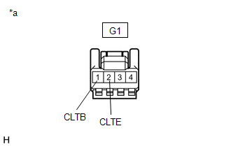
(1) Disconnect the automatic light control sensor (G1).
|
(2) Measure the voltage according to the value(s) in the table below. Standard Voltage:
If the specified condition is not met, replace the vehicle wire harness. |
|
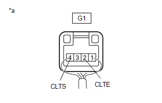
(b) Check the resistance.
(1) Measure the resistance according to the value(s) in the table below.
Standard Resistance:
|
Tester Connection |
Switch Condition |
Specified Condition |
|---|---|---|
|
G1-2(CLTE) - Body ground |
Always |
Below 1 Ω |
If the specified condition is not met, replace the vehicle wire harness.
(c) Check the automatic light control sensor.
(1) Connect the automatic light control sensor (G1).
|
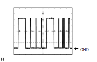
(2) Check the waveform Use the oscilloscope and check the waveform in the terminal spaces. NOTICE: With the connector connected as is, check from the rear side of the connector. Standard:
If the specified condition is not met, replace the solar sensor. |
|
|
(3) Waveform
The communication waveform changes according to the surrounding brightness. |
|
 Components
COMPONENTS
ILLUSTRATION
*1
AUTOMATIC LIGHT CONTROL SENSOR
*2
DEFROSTER NOZZLE ASSEMBLY
...
 Removal
REMOVAL
PROCEDURE
1. REMOVE INSTRUMENT PANEL SAFETY PAD SUB-ASSEMBLY
Click here
2. REMOVE DEFROSTER NOZZLE ASSEMBLY
Click here
3. REMOVE AUTOMATIC LIGHT CONTROL SENSOR
...
Other materials:
Toyota CH-R Service Manual > Continuously Variable Transaxle Fluid: Precaution
PRECAUTION
IGNITION SWITCH EXPRESSIONS
(a) The type of ignition switch used on this model differs depending on the specifications
of the vehicle. The expressions listed in the table below are used in this section.
Expression
Ignition Switch (Position)
Engine Swi ...
Toyota CH-R Owners Manual > Operating the lights and wipers: Windshield wipers and washer
Operating the wiper lever
Operate
lever as follows to select the wiper operation.
Intermittent windshield wipers with interval adjuster
When intermittent windshield wiper operation is selected, the wiper interval
can be also adjusted.
OFF *1 or
*2
Off
INT *1 or
*2
Intermittent w ...
Toyota C-HR (AX20) 2023-2026 Owner's Manual
Toyota CH-R Owners Manual
- For safety and security
- Instrument cluster
- Operation of each component
- Driving
- Interior features
- Maintenance and care
- When trouble arises
- Vehicle specifications
- For owners
Toyota CH-R Service Manual
- Introduction
- Maintenance
- Audio / Video
- Cellular Communication
- Navigation / Multi Info Display
- Park Assist / Monitoring
- Brake (front)
- Brake (rear)
- Brake Control / Dynamic Control Systems
- Brake System (other)
- Parking Brake
- Axle And Differential
- Drive Shaft / Propeller Shaft
- K114 Cvt
- 3zr-fae Battery / Charging
- Networking
- Power Distribution
- Power Assist Systems
- Steering Column
- Steering Gear / Linkage
- Alignment / Handling Diagnosis
- Front Suspension
- Rear Suspension
- Tire / Wheel
- Tire Pressure Monitoring
- Door / Hatch
- Exterior Panels / Trim
- Horn
- Lighting (ext)
- Mirror (ext)
- Window / Glass
- Wiper / Washer
- Door Lock
- Heating / Air Conditioning
- Interior Panels / Trim
- Lighting (int)
- Meter / Gauge / Display
- Mirror (int)
- Power Outlets (int)
- Pre-collision
- Seat
- Seat Belt
- Supplemental Restraint Systems
- Theft Deterrent / Keyless Entry

0.007