Toyota CH-R Service Manual: Network Gateway Ecu
Components
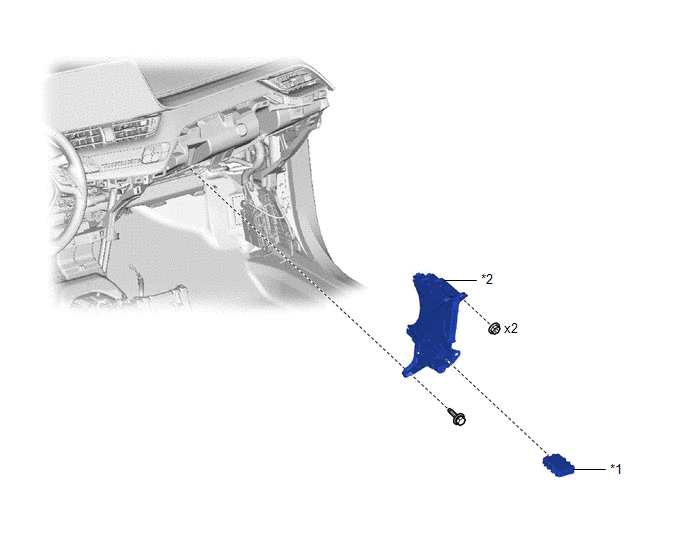
COMPONENTS
ILLUSTRATION
|
*1 |
CENTRAL GATEWAY ECU (NETWORK GATEWAY ECU) |
*2 |
ECU INTEGRATION BOX RH |
Removal
REMOVAL
PROCEDURE
1. REMOVE NO. 2 INSTRUMENT PANEL LOWER FINISH PANEL
Click here
.gif)
2. REMOVE ECU INTEGRATION BOX RH
|
(a) Disconnect the 4 connectors. |
|
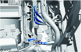
(b) Using a clip remover, disengage the wire harness clamp.
|
(c) Remove the bolt, 2 nuts and ECU integration box RH. |
|
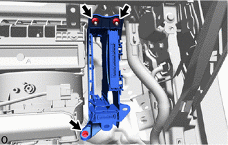
3. REMOVE CENTRAL GATEWAY ECU (NETWORK GATEWAY ECU)
(a) Disengage the claws to remove the central gateway ECU (network gateway ECU).
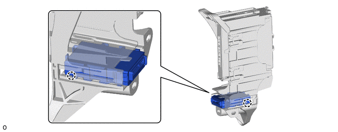
NOTICE:
- If the ECU integration box RH is deformed or damaged, replace it.
- Do not bend the claws more than necessary.
Installation
INSTALLATION
CAUTION / NOTICE / HINT
PROCEDURE
1. INSTALL CENTRAL GATEWAY ECU (NETWORK GATEWAY ECU)
(a) Engage the claws to install the central gateway ECU (network gateway ECU).
.png)
NOTICE:
Make sure that the central gateway ECU (network gateway ECU) is securely installed.
2. INSTALL ECU INTEGRATION BOX RH
(a) Install the ECU integration box RH with the 2 nuts and bolt.
|
(b) Engage the wire harness clamp. |
|
.png)
(c) Connect the 4 connectors.
3. INSTALL NO. 2 INSTRUMENT PANEL LOWER FINISH PANEL
Click here
.gif)
 LIN Communication Bus Malfunction (B2325)
DESCRIPTION
If the main body ECU (multiplex network body ECU) detects a communication error
with an ECU connected to the door bus lines for 7 seconds or more, DTC B2325 will
be stored.
...

Other materials:
Toyota CH-R Service Manual > Audio And Visual System(for Radio And Display Type): Illumination Circuit
DESCRIPTION
Power is supplied to the radio and display receiver assembly and steering pad
switch assembly illumination when the light control switch is in the tail or head
position.
WIRING DIAGRAM
CAUTION / NOTICE / HINT
NOTICE:
The vehicle is equipped with a Supplemental Restrain ...
Toyota CH-R Service Manual > Compressor(for Denso Made): Installation
INSTALLATION
PROCEDURE
1. ADJUST COMPRESSOR OIL
(a) When replacing the compressor with pulley assembly with a new one,
gradually discharge the refrigerant gas from the service valve. Then drain
the following amount of oil from the new compressor with pulley assembly
before ...
Toyota C-HR (AX20) 2023-2026 Owner's Manual
Toyota CH-R Owners Manual
- For safety and security
- Instrument cluster
- Operation of each component
- Driving
- Interior features
- Maintenance and care
- When trouble arises
- Vehicle specifications
- For owners
Toyota CH-R Service Manual
- Introduction
- Maintenance
- Audio / Video
- Cellular Communication
- Navigation / Multi Info Display
- Park Assist / Monitoring
- Brake (front)
- Brake (rear)
- Brake Control / Dynamic Control Systems
- Brake System (other)
- Parking Brake
- Axle And Differential
- Drive Shaft / Propeller Shaft
- K114 Cvt
- 3zr-fae Battery / Charging
- Networking
- Power Distribution
- Power Assist Systems
- Steering Column
- Steering Gear / Linkage
- Alignment / Handling Diagnosis
- Front Suspension
- Rear Suspension
- Tire / Wheel
- Tire Pressure Monitoring
- Door / Hatch
- Exterior Panels / Trim
- Horn
- Lighting (ext)
- Mirror (ext)
- Window / Glass
- Wiper / Washer
- Door Lock
- Heating / Air Conditioning
- Interior Panels / Trim
- Lighting (int)
- Meter / Gauge / Display
- Mirror (int)
- Power Outlets (int)
- Pre-collision
- Seat
- Seat Belt
- Supplemental Restraint Systems
- Theft Deterrent / Keyless Entry

0.0071