
Toyota CH-R Service Manual: Roof Drip Side Finish Moulding
Components
COMPONENTS
ILLUSTRATION
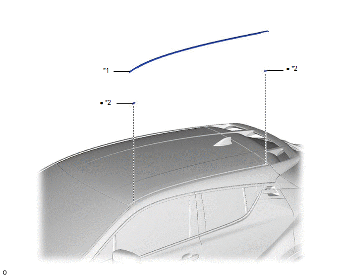
|
*1 |
CENTER ROOF DRIP SIDE FINISH MOULDING |
*2 |
NO. 1 ROOF DRIP SIDE FINISH MOULDING CLIP |
|
● |
Non-reusable part |
- |
- |
Removal
REMOVAL
CAUTION / NOTICE / HINT
HINT:
- Use the same procedure for the RH side and LH side.
- The following procedure is for the LH side.
PROCEDURE
1. REMOVE CENTER ROOF DRIP SIDE FINISH MOULDING
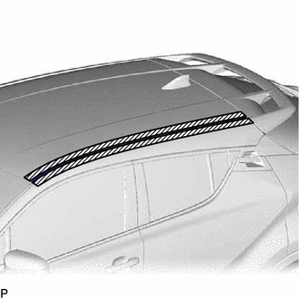
(a) Apply protective tape around the center roof drip side finish moulding.
.png) |
Protective Tape |
|
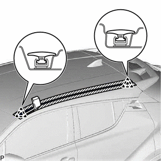
(b) Using a moulding remover D, disengage the 2 clips to remove the center roof drip side finish moulding. NOTICE:
|
|
Installation
INSTALLATION
CAUTION / NOTICE / HINT
HINT:
- Use the same procedure for the RH side and LH side.
- The following procedure is for the LH side.
PROCEDURE
1. INSTALL NO. 1 ROOF DRIP SIDE FINISH MOULDING CLIP
NOTICE:
When installing new roof drip side finish moulding clips, remove any double-sided tape remaining where the roof drip side finish moulding clips will be installed on the vehicle body and clean the vehicle body with a non-residue solvent.
|
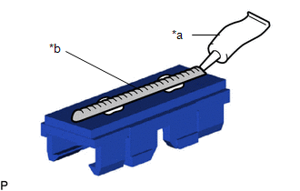
(a) Apply a 2 to 3 mm (0.0787 to 0.118 in.) bead of adhesive (3M DP-105 or equivalent) to each new roof drip side finish moulding clip. HINT: Adhesive strength (tensile strength): 13.7 MPa (140.0 kgf/cm2, 1987 psi) or more (when the temperature is 23°C (73°F).) |
|
(b) Install the roof drip side finish moulding clips to the positions on the roof panel shown in the illustration. Determine the locations and firmly press and install the roof drip side finish moulding clips.
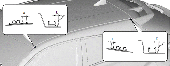
Standard Measurement:
|
Area |
Measurement |
Area |
Measurement |
|---|---|---|---|
|
A |
6.1 mm (0.240 in.) |
B |
2.4 mm (0.0945 in.) |
|
C |
2.9 mm (0.114 in.) |
D |
2.5 mm (0.0984 in.) |
(c) Install the roof drip side finish moulding when 40 minutes or more have elapsed since the roof drip side finish moulding clips were installed.
HINT:
- Initial hardening time: 40 minutes
- Complete hardening time: 24 hours
2. INSTALL CENTER ROOF DRIP SIDE FINISH MOULDING
(a) Engage the 2 clips to install the center roof drip side finish moulding as shown in the illustration.
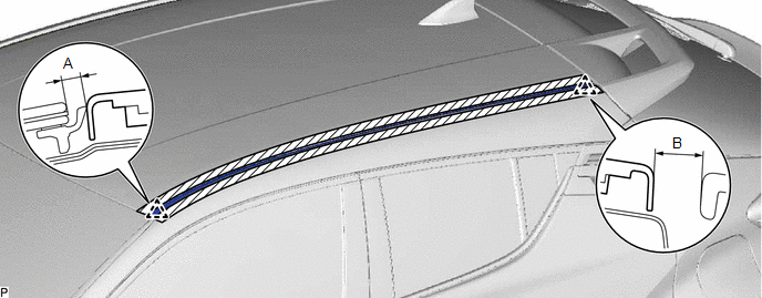
Standard Measurement:
|
Area |
Measurement |
Area |
Measurement |
|---|---|---|---|
|
A |
4.0 mm (0.157 in.) |
B |
9.7 mm (0.382 in.) |
 Installation
INSTALLATION
CAUTION / NOTICE / HINT
HINT:
Use the same procedure for the RH side and LH side.
The following procedure is for the LH side.
PROCEDURE
1. INSTALL ROCKER PANEL MOUL ...
 Wheel Opening Moulding(for Front)
Components
COMPONENTS
ILLUSTRATION
*1
FRONT FENDER MOULDING SUB-ASSEMBLY
-
-
Removal
REMOVAL
CAUTION / NOTICE / HINT
HINT:
Us ...
Other materials:
Toyota CH-R Service Manual > Rear Door Courtesy Switch: Removal
REMOVAL
CAUTION / NOTICE / HINT
The necessary procedures (adjustment, calibration, initialization, or registration)
that must be performed after parts are removed, installed, or replaced during the
rear door courtesy switch removal/installation are shown below.
Necessary Procedures After Part ...
Toyota CH-R Service Manual > 3zr-fae Oil And Oil Filter: Replacement
REPLACEMENT
CAUTION / NOTICE / HINT
CAUTION:
Prolonged and repeated contact with engine oil will result in the removal
of natural oils from the skin, leading to dryness, irritation and dermatitis.
In addition, used engine oil contains potentially harmful contaminants which
may ...
Toyota C-HR (AX20) 2023-2026 Owner's Manual
Toyota CH-R Owners Manual
- For safety and security
- Instrument cluster
- Operation of each component
- Driving
- Interior features
- Maintenance and care
- When trouble arises
- Vehicle specifications
- For owners
Toyota CH-R Service Manual
- Introduction
- Maintenance
- Audio / Video
- Cellular Communication
- Navigation / Multi Info Display
- Park Assist / Monitoring
- Brake (front)
- Brake (rear)
- Brake Control / Dynamic Control Systems
- Brake System (other)
- Parking Brake
- Axle And Differential
- Drive Shaft / Propeller Shaft
- K114 Cvt
- 3zr-fae Battery / Charging
- Networking
- Power Distribution
- Power Assist Systems
- Steering Column
- Steering Gear / Linkage
- Alignment / Handling Diagnosis
- Front Suspension
- Rear Suspension
- Tire / Wheel
- Tire Pressure Monitoring
- Door / Hatch
- Exterior Panels / Trim
- Horn
- Lighting (ext)
- Mirror (ext)
- Window / Glass
- Wiper / Washer
- Door Lock
- Heating / Air Conditioning
- Interior Panels / Trim
- Lighting (int)
- Meter / Gauge / Display
- Mirror (int)
- Power Outlets (int)
- Pre-collision
- Seat
- Seat Belt
- Supplemental Restraint Systems
- Theft Deterrent / Keyless Entry

0.0102