Toyota CH-R Service Manual: Wheel Opening Moulding(for Front)
Components
COMPONENTS
ILLUSTRATION
|
*1 |
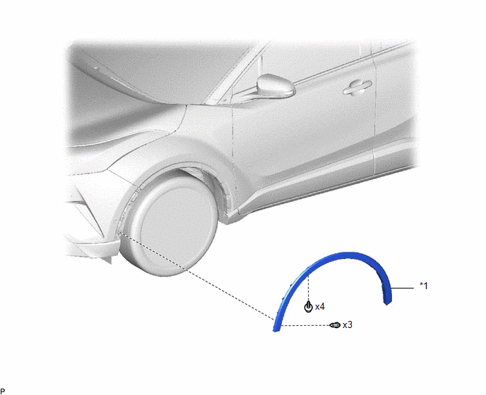
FRONT FENDER MOULDING SUB-ASSEMBLY |
- |
- |
Removal
REMOVAL
CAUTION / NOTICE / HINT
HINT:
- Use the same procedure for the RH and LH sides.
- The procedure listed below is for the LH side.
PROCEDURE
1. REMOVE FRONT FENDER MOULDING SUB-ASSEMBLY
(a) Remove the 3 clips and 5 screws.
(b) Apply protective tape around the front fender moulding sub-assembly.
.png) |
Protective Tape |
|
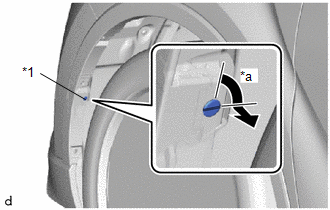
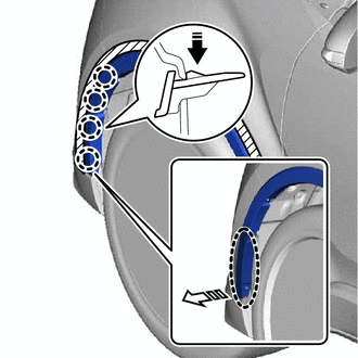
(c) Using a screwdriver, turn the pin 90 degrees and remove the 2 pin hold clips. HINT: Use the same procedure for the RH side and LH side. |
|
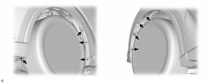
(d) Pull back the edge of the front fender liner and disengage the claws by pushing the area indicated by the arrow in the illustration with a finger.
.png) |
Place Hand Here |
.png)
|
Remove in this Direction (1) |
.png) |
Remove in this Direction (2) |
NOTICE:
- Do not apply excessive force when pulling back the front fender liner.
- To avoid damaging the claws, do not forcibly pull the front fender moulding sub-assembly.
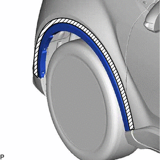
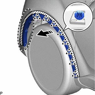
(e) Disengage the clips to remove the front fender moulding sub-assembly as shown in the illustration.
|
|
Place Hand Here |
|
|
Remove in this Direction |
Installation
INSTALLATION
CAUTION / NOTICE / HINT
HINT:
- Use the same procedure for the RH and LH sides.
- The procedure listed below is for the LH side.
PROCEDURE
1. INSTALL FRONT FENDER MOULDING SUB-ASSEMBLY
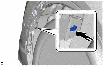
(a) Install the pin hold clip as shown in the illustration.
.png) |
Install in this Direction |
NOTICE:
Insert the pin hold clip with the slot aligned vertically.
Do not rotate the clip after inserting it.
After installation, confirm that the slot is aligned vertically.
HINT:
Use the same procedure for the RH side and LH side.
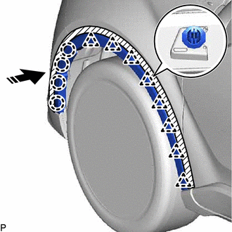
(b) Engage the clips and claws to install the front fender moulding sub-assembly as shown in the illustration.
|
|
Install in this Direction |
(c) Install the 3 clips and 5 screws.
(d) Remove the protective tape.
 Roof Drip Side Finish Moulding
Components
COMPONENTS
ILLUSTRATION
*1
CENTER ROOF DRIP SIDE FINISH MOULDING
*2
NO. 1 ROOF DRIP SIDE FINISH MOULDING CLIP
●
...

Other materials:
Toyota CH-R Service Manual > Side Airbag Sensor(for Center Pillar): Removal
REMOVAL
CAUTION / NOTICE / HINT
The necessary procedures (adjustment, calibration, initialization, or registration)
that must be performed after parts are removed, installed, or replaced during the
side airbag sensor removal/installation are shown below.
Necessary Procedure After Parts Remove ...
Toyota CH-R Service Manual > Audio And Visual System(for Radio And Display Type): Satellite Radio Broadcast cannot be Received
CAUTION / NOTICE / HINT
NOTICE:
Some satellite radio broadcasts require payment. A contract must be made between
a satellite radio company and the user. If the contract expires, it will not be
possible to listen to the broadcast.
WIRING DIAGRAM
for TMMT Made
for TMC Made
PROCEDURE
...
Toyota C-HR (AX20) 2023-2026 Owner's Manual
Toyota CH-R Owners Manual
- For safety and security
- Instrument cluster
- Operation of each component
- Driving
- Interior features
- Maintenance and care
- When trouble arises
- Vehicle specifications
- For owners
Toyota CH-R Service Manual
- Introduction
- Maintenance
- Audio / Video
- Cellular Communication
- Navigation / Multi Info Display
- Park Assist / Monitoring
- Brake (front)
- Brake (rear)
- Brake Control / Dynamic Control Systems
- Brake System (other)
- Parking Brake
- Axle And Differential
- Drive Shaft / Propeller Shaft
- K114 Cvt
- 3zr-fae Battery / Charging
- Networking
- Power Distribution
- Power Assist Systems
- Steering Column
- Steering Gear / Linkage
- Alignment / Handling Diagnosis
- Front Suspension
- Rear Suspension
- Tire / Wheel
- Tire Pressure Monitoring
- Door / Hatch
- Exterior Panels / Trim
- Horn
- Lighting (ext)
- Mirror (ext)
- Window / Glass
- Wiper / Washer
- Door Lock
- Heating / Air Conditioning
- Interior Panels / Trim
- Lighting (int)
- Meter / Gauge / Display
- Mirror (int)
- Power Outlets (int)
- Pre-collision
- Seat
- Seat Belt
- Supplemental Restraint Systems
- Theft Deterrent / Keyless Entry

0.0073