Toyota CH-R Service Manual: Installation
INSTALLATION
CAUTION / NOTICE / HINT
HINT:
- Use the same procedure for the RH side and LH side.
- The following procedure is for the LH side.
PROCEDURE
1. INSTALL REAR SUSPENSION ARM BRACKET
(a) Temporarily install the rear suspension arm bracket to the rear trailing arm assembly with the bolt and nut.
NOTICE:
- Because the bolt has its own stopper, do not turn the bolt. Tighten the nut with the bolt secured.
- Insert the bolt from the inside of the vehicle.
|
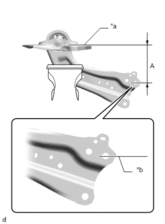
(b) Position the rear trailing arm assembly as shown in the illustration. Reference Length (A): 150 mm (5.91 in.) |
|
(c) Fully tighten the nut.
Torque:
120 N·m {1224 kgf·cm, 89 ft·lbf}
NOTICE:
Because the bolt has its own stopper, do not turn the bolt. Tighten the nut with the bolt secured.
2. INSTALL NO. 1 REAR SUSPENSION SUPPORT COVER
(a) Engage the 3 claws to install the NO. 1 rear suspension support cover.
3. INSTALL REAR TRAILING ARM ASSEMBLY
(a) Using a transmission jack and a wooden block, support the rear No. 2 suspension arm assembly.
NOTICE:
- When jacking up the rear No. 2 suspension arm assembly, be sure to jack it up slowly.
- Make sure to perform this operation with the vehicle kept as low as possible.
(b) Install the rear trailing arm assembly to the vehicle with the 4 bolts.
Torque:
90 N·m {918 kgf·cm, 66 ft·lbf}
(c) Install the rear trailing arm assembly to the rear axle carrier sub-assembly with the 2 bolts.
Torque:
135 N·m {1377 kgf·cm, 100 ft·lbf}
4. INSTALL NO. 2 PARKING BRAKE WIRE ASSEMBLY
(a) Engage the clamp.
(b) Install the No. 2 parking brake wire assembly to the rear trailing arm assembly with the nut.
Torque:
15.5 N·m {158 kgf·cm, 11 ft·lbf}
(c) Connect the No. 2 parking brake wire connector to the rear axle hub and bearing assembly.
5. INSTALL REAR STABILIZER LINK ASSEMBLY
Click here
.gif)
6. INSTALL REAR WHEEL
Click here
7. INSPECT AND ADJUST REAR WHEEL ALIGNMENT
Click here
 Removal
REMOVAL
CAUTION / NOTICE / HINT
The necessary procedures (adjustment, calibration, initialization, or registration)
that must be performed after parts are removed and installed, or replaced during ...
 Rear Upper Arm
Components
COMPONENTS
ILLUSTRATION
*1
REAR SUSPENSION MEMBER SUB-ASSEMBLY
*2
REAR UPPER CONTROL ARM ASSEMBLY LH
*3
REAR U ...
Other materials:
Toyota CH-R Service Manual > Condenser: Disassembly
DISASSEMBLY
PROCEDURE
1. REMOVE COOLER DRYER (for VALEO Made)
(a) Using a T55 "TORX" socket wrench, remove the cap from the modulator.
*a
Modulator
...
Toyota CH-R Service Manual > Front Airbag Sensor: Removal
REMOVAL
CAUTION / NOTICE / HINT
The necessary procedures (adjustment, calibration, initialization, or registration)
that must be performed after parts are removed, installed, or replaced during the
front airbag sensor removal/installation are shown below.
Necessary Procedure After Parts Remov ...
Toyota C-HR (AX20) 2023-2026 Owner's Manual
Toyota CH-R Owners Manual
- For safety and security
- Instrument cluster
- Operation of each component
- Driving
- Interior features
- Maintenance and care
- When trouble arises
- Vehicle specifications
- For owners
Toyota CH-R Service Manual
- Introduction
- Maintenance
- Audio / Video
- Cellular Communication
- Navigation / Multi Info Display
- Park Assist / Monitoring
- Brake (front)
- Brake (rear)
- Brake Control / Dynamic Control Systems
- Brake System (other)
- Parking Brake
- Axle And Differential
- Drive Shaft / Propeller Shaft
- K114 Cvt
- 3zr-fae Battery / Charging
- Networking
- Power Distribution
- Power Assist Systems
- Steering Column
- Steering Gear / Linkage
- Alignment / Handling Diagnosis
- Front Suspension
- Rear Suspension
- Tire / Wheel
- Tire Pressure Monitoring
- Door / Hatch
- Exterior Panels / Trim
- Horn
- Lighting (ext)
- Mirror (ext)
- Window / Glass
- Wiper / Washer
- Door Lock
- Heating / Air Conditioning
- Interior Panels / Trim
- Lighting (int)
- Meter / Gauge / Display
- Mirror (int)
- Power Outlets (int)
- Pre-collision
- Seat
- Seat Belt
- Supplemental Restraint Systems
- Theft Deterrent / Keyless Entry

0.0097