Toyota CH-R Service Manual: Removal
REMOVAL
CAUTION / NOTICE / HINT
The necessary procedures (adjustment, calibration, initialization, or registration) that must be performed after parts are removed and installed, or replaced during rear trailing arm assembly removal/installation are shown below.
Necessary Procedures After Parts Removed/Installed/Replaced|
Replaced Part or Performed Procedure |
Necessary Procedure |
Effect/Inoperative Function when Necessary Procedure not Performed |
Link |
|---|---|---|---|
|
Rear wheel alignment adjustment |
|
|
|
HINT:
- Use the same procedure for the RH side and LH side.
- The following procedure is for the LH side.
PROCEDURE
1. REMOVE REAR WHEEL
Click here
.gif)
2. SEPARATE NO. 2 PARKING BRAKE WIRE ASSEMBLY
|
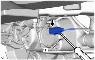
(a) Using a screwdriver with its tip wrapped in protective tape, disconnect the No. 2 parking brake wire connector from the rear axle hub and bearing assembly. NOTICE: Be careful not to damage the rear axle hub and bearing assembly and connector cover. |
|
|
(b) Disengage the clamp. |
|
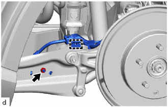
(c) Remove the nut to separate the No. 2 parking brake wire assembly from the rear trailing arm assembly.
3. REMOVE REAR STABILIZER LINK ASSEMBLY
Click here
4. REMOVE REAR TRAILING ARM ASSEMBLY
|
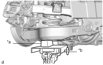
(a) Using a transmission jack and a wooden block, support the rear No. 2 suspension arm assembly. NOTICE:
|
|
|
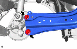
(b) Remove the 2 bolts to separate the rear trailing arm assembly from the rear axle carrier sub-assembly. |
|
|
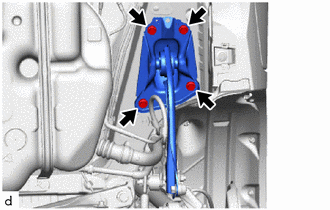
(c) Remove the 4 bolts and rear trailing arm assembly. |
|
5. REMOVE NO. 1 REAR SUSPENSION SUPPORT COVER
|
(a) Secure the rear trailing arm assembly in a vise using aluminum plates. NOTICE: Do not overtighten the vise. |
|
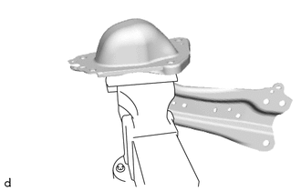
|
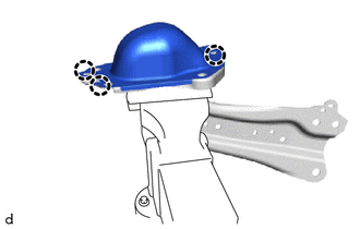
(b) Disengage the 3 claws to remove the NO. 1 rear suspension support cover. |
|
6. REMOVE REAR SUSPENSION ARM BRACKET
|
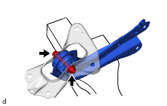
(a) Remove the bolt, nut and rear suspension arm bracket from the rear trailing arm assembly. NOTICE: Because the bolt has its own stopper, do not turn the bolt. Loosen the nut with the bolt secured. |
|
 Components
COMPONENTS
ILLUSTRATION
*1
NO. 2 PARKING BRAKE WIRE ASSEMBLY
*2
REAR STABILIZER LINK ASSEMBLY
*3
REAR TRAILING ARM ASSEMBLY
...
 Installation
INSTALLATION
CAUTION / NOTICE / HINT
HINT:
Use the same procedure for the RH side and LH side.
The following procedure is for the LH side.
PROCEDURE
1. INSTALL REAR SUSPENSION A ...
Other materials:
Toyota CH-R Service Manual > Power Window Control System: Dtc Check / Clear
DTC CHECK / CLEAR
CHECK DTC
(a) Connect the Techstream to the DLC3.
(b) Turn the ignition switch to ON.
(c) Turn the Techstream on.
(d) Enter the following menus: Body Electrical / (desired system) / Trouble Codes.
Body Electrical > Master Switch > Trouble Codes Body Electrical > D-Do ...
Toyota CH-R Service Manual > Meter / Gauge System: Precaution
PRECAUTION
FUEL RECEIVER GAUGE OPERATION
(a) OPERATION
The combination meter assembly uses the fuel injection volume signal from the
ECM, fuel sender gauge assembly to detect the amount of fuel remaining in the fuel
tank assembly. Each gauge assembly has a variable resistor whose resistance c ...
Toyota C-HR (AX20) 2023-2026 Owner's Manual
Toyota CH-R Owners Manual
- For safety and security
- Instrument cluster
- Operation of each component
- Driving
- Interior features
- Maintenance and care
- When trouble arises
- Vehicle specifications
- For owners
Toyota CH-R Service Manual
- Introduction
- Maintenance
- Audio / Video
- Cellular Communication
- Navigation / Multi Info Display
- Park Assist / Monitoring
- Brake (front)
- Brake (rear)
- Brake Control / Dynamic Control Systems
- Brake System (other)
- Parking Brake
- Axle And Differential
- Drive Shaft / Propeller Shaft
- K114 Cvt
- 3zr-fae Battery / Charging
- Networking
- Power Distribution
- Power Assist Systems
- Steering Column
- Steering Gear / Linkage
- Alignment / Handling Diagnosis
- Front Suspension
- Rear Suspension
- Tire / Wheel
- Tire Pressure Monitoring
- Door / Hatch
- Exterior Panels / Trim
- Horn
- Lighting (ext)
- Mirror (ext)
- Window / Glass
- Wiper / Washer
- Door Lock
- Heating / Air Conditioning
- Interior Panels / Trim
- Lighting (int)
- Meter / Gauge / Display
- Mirror (int)
- Power Outlets (int)
- Pre-collision
- Seat
- Seat Belt
- Supplemental Restraint Systems
- Theft Deterrent / Keyless Entry

0.0076