Toyota CH-R Service Manual: Open in ABS Motor Relay Circuit (C146C)
DESCRIPTION
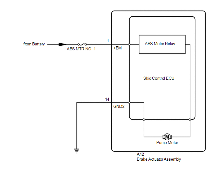
The ABS motor relay supplies power to the pump motor. While the ABS is activated, the skid control ECU turns the ABS motor relay on to operate the pump motor.
If the voltage supplied to the ABS motor relay (+BM) is too low due to low voltage from the battery or alternator, this DTC may be stored.
|
DTC No. |
Detection Item |
DTC Detection Condition |
Trouble Area |
|---|---|---|---|
|
C146C |
Open in ABS Motor Relay Circuit |
Any of the following is detected:
|
|
|
Vehicle Condition |
||||
|---|---|---|---|---|
|
Pattern 1 |
Pattern 2 |
Pattern 3 |
||
|
Diagnosis Condition |
- |
- |
- |
- |
|
Malfunction Status |
When the ABS motor relay is actuated, voltage is not supplied to the pump motor. |
○ |
- |
- |
|
When the ABS motor relay is not actuated, voltage in the pump motor is high. |
- |
○ |
- |
|
|
The skid control ECU judges that pump motor operation is abnormal. |
- |
- |
○ |
|
|
Detection Time |
- |
- |
- |
|
|
Number of Trips |
1 trip |
1 trip |
1 trip |
|
HINT:
DTC will be output when conditions for either of the patterns in the table above are met.
WIRING DIAGRAM
CAUTION / NOTICE / HINT
NOTICE:
- When replacing the skid control ECU (brake actuator assembly), perform
system variant learning.
Click here
.gif)
- Inspect the fuses for circuits related to this system before performing the following procedure.
HINT:
When C1241 and/or C1417 is output together with C146C, inspect and repair the trouble areas indicated by C1241 and/or C1417 first.
for C1241: Click here
for C1417: Click here
PROCEDURE
|
1. |
PERFORM ACTIVE TEST USING TECHSTREAM (ABS MOTOR RELAY) |
(a) Connect the Techstream to the DLC3.
(b) Start the engine.
(c) Select the Active Test using the Techstream.
Click here
|
Tester Display |
Measurement Item |
Control Range |
Diagnostic Note |
|---|---|---|---|
|
Motor Relay |
ABS motor relay |
Relay ON/OFF |
Operating sound of motor can be heard |
|
Tester Display |
|---|
|
Motor Relay |
(d) Check the operating sound of the pump motor when operating it using the Techstream.
|
Result |
Proceed to |
|---|---|
|
Operating sound is heard. |
A |
|
Operating sound is not heard. |
B |
| B | .gif) |
GO TO STEP 3 |
|
.gif)
|
2. |
RECONFIRM DTC |
HINT:
This DTC is stored when a problem is identified in the skid control ECU (brake actuator assembly).
The ABS motor relay is in the skid control ECU (brake actuator assembly).
Therefore, motor relay inspection and motor relay unit inspection cannot be performed. Be sure to check if the DTC is output again before replacing the skid control ECU (brake actuator assembly).
(a) Turn the ignition switch off.
(b) Clear the DTCs.
Click here
(c) Turn the ignition switch off.
(d) Start the engine.
(e) Drive the vehicle at a speed of 40 km/h (25 mph) or more for 30 seconds or more.
(f) Check if the same DTC is output.
Click here
|
Result |
Proceed to |
|---|---|
|
DTC C146C is not output. |
A |
|
DTC C146C is output. |
B |
HINT:
- If a speed signal of 40 km/h (25 mph) or more is received by the skid control ECU (brake actuator assembly) with the ignition switch ON, the skid control ECU (brake actuator assembly) performs self diagnosis of the motor circuit.
- If the normal system code is output (no DTCs are output), slightly jiggle the connectors, wire harness, and fuses of the skid control ECU (brake actuator assembly).
- If any DTCs are output while jiggling a connector or wire harness of the skid control ECU (brake actuator assembly), inspect and repair the connector or wire harness.
- If no DTCs were output when reconfirming DTCs, checking for intermittent problems is necessary because it is suspected that the original DTCs were stored due to the poor connection of a connector terminal.
| A | |
USE SIMULATION METHOD TO CHECK
|
| B | |
REPLACE BRAKE ACTUATOR ASSEMBLY |
|
3. |
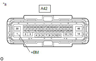
CHECK HARNESS AND CONNECTOR (+BM TERMINAL) |
|
(a) Make sure that there is no looseness at the locking part and the connecting part of the connector. |
|
(b) Disconnect the A42 skid control ECU (brake actuator assembly) connector.
(c) Measure the voltage according to the value(s) in the table below.
Standard Voltage:
|
Tester Connection |
Condition |
Specified Condition |
|---|---|---|
|
A42-1 (+BM) - Body ground |
Always |
11 to 14 V |
| NG | |
REPAIR OR REPLACE HARNESS OR CONNECTOR (+BM CIRCUIT) |
|
|
4. |
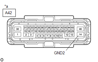
CHECK HARNESS AND CONNECTOR (GND2 TERMINAL) |
|
(a) Measure the resistance according to the value(s) in the table below. Standard Resistance:
|
|
| OK | |
REPLACE BRAKE ACTUATOR ASSEMBLY |
| NG | |
REPAIR OR REPLACE HARNESS OR CONNECTOR (GND2 CIRCUIT) |
 Diagnostic Trouble Code Chart
DIAGNOSTIC TROUBLE CODE CHART
Vehicle Stability Control System
DTC No.
Detection Item
Link
C1201
Engine Control System Malfunction
...
 SM Solenoid Circuit (C1225-C1228,C1468,C1469,C146A,C146B)
DESCRIPTION
These solenoids turn on when signals are received from the skid control ECU (brake
actuator assembly) and they control the pressure acting on the wheel cylinders to
control the brakin ...
Other materials:
Toyota CH-R Service Manual > Side Airbag Sensor(for Front Door): Removal
REMOVAL
CAUTION / NOTICE / HINT
The necessary procedures (adjustment, calibration, initialization, or registration)
that must be performed after parts are removed, installed, or replaced during the
door side airbag sensor removal/installation are shown below.
Necessary Procedure After Parts R ...
Toyota CH-R Service Manual > Wireless Door Lock Control System(w/ Smart Key System): No Answer-Back
DESCRIPTION
In some cases, wireless door lock control functions are normal but the hazard
warning light and/or wireless door lock buzzer answer-back function*1 does not operate.
In such cases, hazard warning light and wireless door lock buzzer*1 signal outputs
from the main body ECU (multiple ...
Toyota C-HR (AX20) 2023-2026 Owner's Manual
Toyota CH-R Owners Manual
- For safety and security
- Instrument cluster
- Operation of each component
- Driving
- Interior features
- Maintenance and care
- When trouble arises
- Vehicle specifications
- For owners
Toyota CH-R Service Manual
- Introduction
- Maintenance
- Audio / Video
- Cellular Communication
- Navigation / Multi Info Display
- Park Assist / Monitoring
- Brake (front)
- Brake (rear)
- Brake Control / Dynamic Control Systems
- Brake System (other)
- Parking Brake
- Axle And Differential
- Drive Shaft / Propeller Shaft
- K114 Cvt
- 3zr-fae Battery / Charging
- Networking
- Power Distribution
- Power Assist Systems
- Steering Column
- Steering Gear / Linkage
- Alignment / Handling Diagnosis
- Front Suspension
- Rear Suspension
- Tire / Wheel
- Tire Pressure Monitoring
- Door / Hatch
- Exterior Panels / Trim
- Horn
- Lighting (ext)
- Mirror (ext)
- Window / Glass
- Wiper / Washer
- Door Lock
- Heating / Air Conditioning
- Interior Panels / Trim
- Lighting (int)
- Meter / Gauge / Display
- Mirror (int)
- Power Outlets (int)
- Pre-collision
- Seat
- Seat Belt
- Supplemental Restraint Systems
- Theft Deterrent / Keyless Entry

0.0081