Toyota CH-R Service Manual: Rear Upper Arm
Components
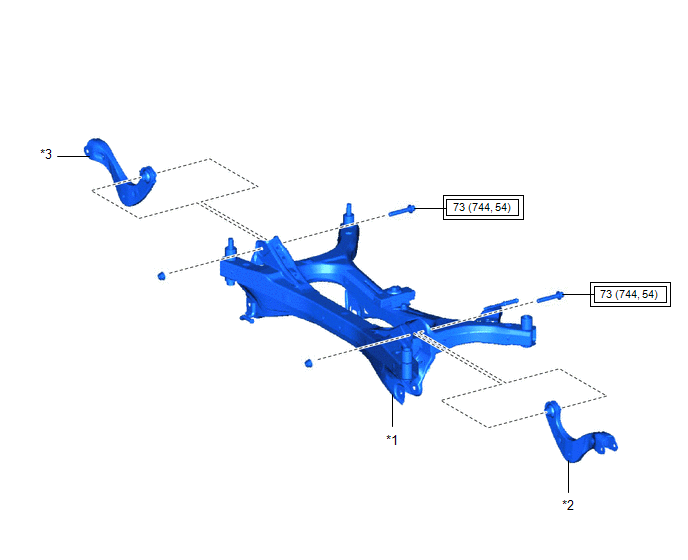
COMPONENTS
ILLUSTRATION
|
*1 |
REAR SUSPENSION MEMBER SUB-ASSEMBLY |
*2 |
REAR UPPER CONTROL ARM ASSEMBLY LH |
|
*3 |
REAR UPPER CONTROL ARM ASSEMBLY RH |
- |
- |
.png) |
Tightening torque for "Major areas involving basic vehicle performance such as moving/turning/stopping" : N*m (kgf*cm, ft.*lbf) |
- |
- |
Removal
REMOVAL
CAUTION / NOTICE / HINT
The necessary procedures (adjustment, calibration, initialization, or registration) that must be performed after parts are removed and installed, or replaced during rear upper control arm assembly removal/installation are shown below.
Necessary Procedures After Parts Removed/Installed/Replaced|
Replaced Part or Performed Procedure |
Necessary Procedure |
Effect/Inoperative Function when Necessary Procedure not Performed |
Link |
|---|---|---|---|
|
Rear wheel alignment adjustment |
|
|
|
|
Removal/installation of rear height control sensor sub-assembly LH*1 |
Initialize headlight ECU sub-assembly LH |
Automatic headlight beam level control system |
|
|
Suspension, tires, etc. (The vehicle height changes because of suspension or tire replacement)*1 |
|||
|
Gas leak from exhaust system is repaired |
Inspection After Repair |
|
|
- *1: w/ Height Control Sensor
CAUTION:
To prevent burns, do not touch the engine, exhaust pipe or other high temperature components while the engine is hot.
.png)
PROCEDURE
1. REMOVE REAR SUSPENSION MEMBER SUB-ASSEMBLY
Click here
.gif)
2. REMOVE REAR UPPER CONTROL ARM ASSEMBLY LH
|
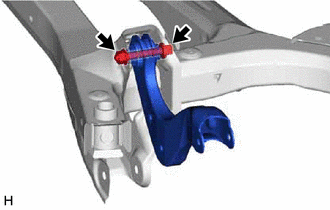
(a) Remove the bolt, nut and rear upper control arm assembly LH from the rear suspension member sub-assembly. NOTICE: Because the nut has its own stopper, do not turn the nut. Loosen the bolt with the nut secured. |
|
3. REMOVE REAR UPPER CONTROL ARM ASSEMBLY RH
HINT:
Perform the same procedure as for the LH side.
Installation
INSTALLATION
PROCEDURE
1. INSTALL REAR UPPER CONTROL ARM ASSEMBLY LH
|
(a) Temporarily install the rear upper control arm assembly LH to the rear suspension member sub-assembly with the bolt and nut. NOTICE:
|
|
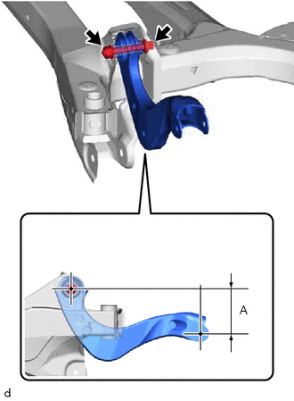
(b) Position the rear upper control arm assembly LH as shown in the illustration.
Reference Length (A):
17.9 mm (0.705 in.)
(c) Fully tighten the bolt.
Torque:
73 N·m {744 kgf·cm, 54 ft·lbf}
NOTICE:
Because the nut has its own stopper, do not turn the nut. Tighten the bolt with the nut secured.
2. INSTALL REAR UPPER CONTROL ARM ASSEMBLY RH
HINT:
Perform the same procedure as for the LH side.
3. INSTALL REAR SUSPENSION MEMBER SUB-ASSEMBLY
Click here
.gif)
 Installation
INSTALLATION
CAUTION / NOTICE / HINT
HINT:
Use the same procedure for the RH side and LH side.
The following procedure is for the LH side.
PROCEDURE
1. INSTALL REAR SUSPENSION A ...
 Tire / Wheel
...
Other materials:
Toyota CH-R Service Manual > Hood Lock Control Cable Assembly: Removal
REMOVAL
PROCEDURE
1. REMOVE FRONT WHEEL
Click here
2. REMOVE FRONT BUMPER ASSEMBLY
Click here
3. REMOVE FRONT FENDER MOULDING SUB-ASSEMBLY
Click here
4. REMOVE ROCKER PANEL MOULDING LH
Click here
5. REMOVE FRONT FENDER LINER LH
(a) Remove the 2 screws, 7 clips and front fe ...
Toyota CH-R Service Manual > Instrument Panel Speaker: Components
COMPONENTS
ILLUSTRATION
*1
FRONT DOOR OPENING TRIM WEATHERSTRIP
*2
FRONT NO. 2 SPEAKER ASSEMBLY
*3
FRONT PILLAR GARNISH ASSEMBLY
*4
NO. 1 INSTRUMENT PANEL SPEAKER PANEL SUB-ASSEMBLY
...
Toyota C-HR (AX20) 2023-2026 Owner's Manual
Toyota CH-R Owners Manual
- For safety and security
- Instrument cluster
- Operation of each component
- Driving
- Interior features
- Maintenance and care
- When trouble arises
- Vehicle specifications
- For owners
Toyota CH-R Service Manual
- Introduction
- Maintenance
- Audio / Video
- Cellular Communication
- Navigation / Multi Info Display
- Park Assist / Monitoring
- Brake (front)
- Brake (rear)
- Brake Control / Dynamic Control Systems
- Brake System (other)
- Parking Brake
- Axle And Differential
- Drive Shaft / Propeller Shaft
- K114 Cvt
- 3zr-fae Battery / Charging
- Networking
- Power Distribution
- Power Assist Systems
- Steering Column
- Steering Gear / Linkage
- Alignment / Handling Diagnosis
- Front Suspension
- Rear Suspension
- Tire / Wheel
- Tire Pressure Monitoring
- Door / Hatch
- Exterior Panels / Trim
- Horn
- Lighting (ext)
- Mirror (ext)
- Window / Glass
- Wiper / Washer
- Door Lock
- Heating / Air Conditioning
- Interior Panels / Trim
- Lighting (int)
- Meter / Gauge / Display
- Mirror (int)
- Power Outlets (int)
- Pre-collision
- Seat
- Seat Belt
- Supplemental Restraint Systems
- Theft Deterrent / Keyless Entry

0.0071