Toyota CH-R Service Manual: Removal
REMOVAL
CAUTION / NOTICE / HINT
The necessary procedures (adjustment, calibration, initialization, or registration) that must be performed after parts are removed and installed, or replaced during front stabilizer bar removal/installation are shown below.
Necessary Procedures After Parts Removed/Installed/Replaced|
Replaced Part or Performed Procedure |
Necessary Procedure |
Effect/Inoperative Function when Necessary Procedure not Performed |
Link |
|---|---|---|---|
|
Front wheel alignment adjustment |
|
|
|
|
Suspension, tires, etc. (The vehicle height changes because of suspension or tire replacement) |
Initialize No. 1 headlight ECU sub-assembly LH |
Automatic headlight beam level control system |
|
PROCEDURE
1. REMOVE FRONT SUSPENSION CROSSMEMBER SUB-ASSEMBLY
Click here
.gif)
2. REMOVE STEERING LINK ASSEMBLY
|
(a) Remove the 2 bolts, 2 nuts and steering link assembly from the front suspension crossmember sub-assembly. NOTICE: Because the nut has its own stopper, do not turn the nut. Loosen the bolt with the nut secured. |
|
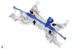
3. REMOVE FRONT STABILIZER LINK ASSEMBLY LH
|
(a) Remove the nut and front stabilizer link assembly LH from the front stabilizer bar LH. |
|
4. REMOVE FRONT STABILIZER LINK ASSEMBLY RH
HINT:
Perform the same procedure as for the LH side.
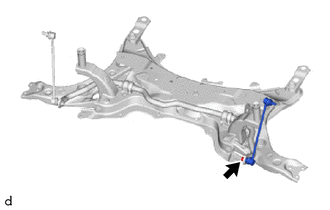
5. REMOVE FRONT NO. 1 STABILIZER BRACKET LH
|
(a) Remove the 2 bolts and front stabilizer bracket LH from the front suspension crossmember sub-assembly. |
|
6. REMOVE FRONT NO. 1 STABILIZER BRACKET RH
HINT:
Perform the same procedure as for the LH side.
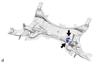
7. REMOVE FRONT STABILIZER BAR
(a) Remove the front stabilizer bar with 2 front stabilizer bar bushings from the front suspension crossmember sub-assembly.
8. REMOVE FRONT STABILIZER BAR BUSHING LH
(a) Remove the front stabilizer bar bushing LH from the front stabilizer bar.
9. REMOVE FRONT STABILIZER BAR BUSHING RH
HINT:
Perform the same procedure as for the LH side.
 Components
COMPONENTS
ILLUSTRATION
*1
FRONT NO. 1 STABILIZER BRACKET LH
*2
FRONT NO. 1 STABILIZER BRACKET RH
*3
FRONT STABILIZER BAR
...
 Inspection
INSPECTION
PROCEDURE
1. INSPECT FRONT STABILIZER LINK ASSEMBLY
(a) Inspect the turning torque of the ball joint.
(1) Secure the front stabilizer link assembly in a vise using aluminum ...
Other materials:
Toyota CH-R Service Manual > Smart Key System(for Entry Function): Data List / Active Test
DATA LIST / ACTIVE TEST
DATA LIST
NOTICE:
In the table below, the values listed under "Normal Condition" are reference
values. Do not depend solely on these reference values when deciding whether
a part is faulty or not.
When using the Techstream with the engine swit ...
Toyota CH-R Service Manual > Rear View Monitor System: Precaution
PRECAUTION
IGNITION SWITCH EXPRESSIONS
(a) The type of ignition switch used on this model differs depending on the specifications
of the vehicle. The expressions listed in the table below are used in this section.
Expression
Ignition Switch (Position)
Engine Swi ...
Toyota C-HR (AX20) 2023-2026 Owner's Manual
Toyota CH-R Owners Manual
- For safety and security
- Instrument cluster
- Operation of each component
- Driving
- Interior features
- Maintenance and care
- When trouble arises
- Vehicle specifications
- For owners
Toyota CH-R Service Manual
- Introduction
- Maintenance
- Audio / Video
- Cellular Communication
- Navigation / Multi Info Display
- Park Assist / Monitoring
- Brake (front)
- Brake (rear)
- Brake Control / Dynamic Control Systems
- Brake System (other)
- Parking Brake
- Axle And Differential
- Drive Shaft / Propeller Shaft
- K114 Cvt
- 3zr-fae Battery / Charging
- Networking
- Power Distribution
- Power Assist Systems
- Steering Column
- Steering Gear / Linkage
- Alignment / Handling Diagnosis
- Front Suspension
- Rear Suspension
- Tire / Wheel
- Tire Pressure Monitoring
- Door / Hatch
- Exterior Panels / Trim
- Horn
- Lighting (ext)
- Mirror (ext)
- Window / Glass
- Wiper / Washer
- Door Lock
- Heating / Air Conditioning
- Interior Panels / Trim
- Lighting (int)
- Meter / Gauge / Display
- Mirror (int)
- Power Outlets (int)
- Pre-collision
- Seat
- Seat Belt
- Supplemental Restraint Systems
- Theft Deterrent / Keyless Entry

0.0103