Toyota CH-R Service Manual: Removal
REMOVAL
CAUTION / NOTICE / HINT
The necessary procedures (adjustment, calibration, initialization, or registration) that must be performed after parts are removed, installed, or replaced during the steering wheel assembly removal/installation are shown below.
Necessary Procedure After Parts Removed/Installed/Replaced|
Replacement Part or Procedure |
Necessary Procedures |
Effects / Inoperative when not performed |
Link |
|---|---|---|---|
|
Disconnect cable from negative battery terminal |
Initialize back door lock |
Power door lock control system |
|
|
Memorize steering angle neutral point |
Lane departure alert system (w/ Steering Control) |
|
|
|
Pre-collision system |
NOTICE:
- Do not replace the spiral cable with sensor sub-assembly with the battery connected and the ignition switch ON.
- Do not rotate the spiral cable with sensor sub-assembly without the steering wheel assembly installed with the battery connected and the ignition switch ON.
- Ensure that the steering wheel assembly is installed and aligned straight when inspecting the steering sensor.
PROCEDURE
1. ALIGN FRONT WHEELS FACING STRAIGHT AHEAD
2. REMOVE HORN BUTTON ASSEMBLY
Click here
.gif)
3. REMOVE STEERING WHEEL ASSEMBLY
|
(a) Disconnect the 2 connectors from the spiral cable with sensor sub-assembly. |
|
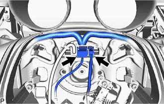
(b) w/ Steering Heater:
|
(1) Disconnect the steering heater connector. |
|
|
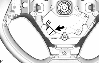
(c) Remove the steering wheel assembly set nut. |
|
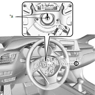
(d) Put matchmarks on the steering wheel assembly and steering main shaft.
|
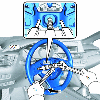
(e) Using SST, remove the steering wheel assembly. SST: 09950-50013 09951-05010 09952-05010 09953-05020 09954-05031 NOTICE: Apply a small amount of grease to the threads and tip of SST (09953-05020) before use. |
|
4. REMOVE LOWER NO. 2 STEERING WHEEL COVER
Click here
5. REMOVE CRUISE CONTROL MAIN SWITCH
Click here
6. REMOVE STEERING PAD SWITCH ASSEMBLY
Click here
 Components
COMPONENTS
ILLUSTRATION
*1
STEERING WHEEL ASSEMBLY
-
-
Tightening torque for "Major areas involving basic vehicle perform ...
 Installation
INSTALLATION
CAUTION / NOTICE / HINT
NOTICE:
Do not replace the spiral cable with sensor sub-assembly with the battery
connected and the ignition switch ON.
Do not rotate the spiral ...
Other materials:
Toyota CH-R Service Manual > Rear Axle Carrier: Removal
REMOVAL
CAUTION / NOTICE / HINT
The necessary procedures (adjustment, calibration, initialization, or registration)
that must be performed after parts are removed and installed, or replaced during
rear axle carrier sub-assembly removal/installation are shown below.
Necessary Procedures After ...
Toyota CH-R Service Manual > Audio / Video: Radio Receiver(for Radio Receiver Type)
Components
COMPONENTS
ILLUSTRATION
*1
INSTRUMENT CLUSTER FINISH CENTER PANEL SUB-ASSEMBLY
*2
RADIO RECEIVER ASSEMBLY WITH BRACKET
ILLUSTRATION
*1
NO. 1 RADIO BRACKET
*2
NO. 2 RADIO BRACKET
...
Toyota C-HR (AX20) 2023-2026 Owner's Manual
Toyota CH-R Owners Manual
- For safety and security
- Instrument cluster
- Operation of each component
- Driving
- Interior features
- Maintenance and care
- When trouble arises
- Vehicle specifications
- For owners
Toyota CH-R Service Manual
- Introduction
- Maintenance
- Audio / Video
- Cellular Communication
- Navigation / Multi Info Display
- Park Assist / Monitoring
- Brake (front)
- Brake (rear)
- Brake Control / Dynamic Control Systems
- Brake System (other)
- Parking Brake
- Axle And Differential
- Drive Shaft / Propeller Shaft
- K114 Cvt
- 3zr-fae Battery / Charging
- Networking
- Power Distribution
- Power Assist Systems
- Steering Column
- Steering Gear / Linkage
- Alignment / Handling Diagnosis
- Front Suspension
- Rear Suspension
- Tire / Wheel
- Tire Pressure Monitoring
- Door / Hatch
- Exterior Panels / Trim
- Horn
- Lighting (ext)
- Mirror (ext)
- Window / Glass
- Wiper / Washer
- Door Lock
- Heating / Air Conditioning
- Interior Panels / Trim
- Lighting (int)
- Meter / Gauge / Display
- Mirror (int)
- Power Outlets (int)
- Pre-collision
- Seat
- Seat Belt
- Supplemental Restraint Systems
- Theft Deterrent / Keyless Entry

0.008