Toyota CH-R Service Manual: Terminals Of Ecu
TERMINALS OF ECU
TERMINAL INSPECTION
|
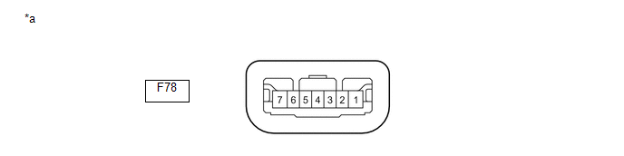
*a |
Component without harness connected (Steering Lock ECU (Steering Lock Actuator or Upper Bracket Assembly)) |
- |
- |
(a) Measure the voltage and resistance according to the value(s) in the table below.
|
Terminal No. (Symbol) |
Input/Output |
Wiring Color |
Terminal Description |
Condition |
Specified Condition |
Related Data List Item |
|---|---|---|---|---|---|---|
|
F78-1 (GND) - Body ground |
- |
W-B - Body ground |
Ground*1 |
Always |
Below 1 Ω |
- |
|
F78-3 (IGEI) - F78-1 (GND) |
Input |
P - W-B |
Steering lock motor activation command signal (motor activation command signal sent from certification ECU (smart key ECU assembly)) |
Any door opened when conditions below met, and then steering lock motor activated:
|
Pulse generation (see waveform) |
Smart Key
|
|
F78-4 (SLP1) - F78-1 (GND) |
Output |
G - W-B |
Steering lock bar position signal (output signal from steering unlock sensor) |
Steering locked → unlocked |
11 to 14 V → Below 1.5 V |
Smart Key
|
|
F78-5 (LIN) - F78-1 (GND) |
Input/Output |
V - W-B |
LIN communication line |
- |
- |
Smart Key
|
|
F78-6 (IG2) - F78-1 (GND) |
Input |
B - W-B |
Power source mode signal (IG2 power supply input for entire steering lock actuator or upper bracket assembly)*1 |
Engine switch off → engine switch on (IG) |
Below 1 V → 11 to 14 V |
- |
|
F78-7 (B) - Body ground |
Input |
L - Body ground |
Power source*1 |
Always |
11 to 14 V |
- |
- *1: When there is a problem with the power source input, the certification ECU (smart key ECU assembly) may store DTC B2786.
NOTICE:
There is 1 motor and 2 sensors built into the steering lock actuator or upper bracket assembly.
HINT:
- When taking measurements when the lock motor is stopped, it is not necessary to perform any operations.
- In order to take measurements when the lock motor is operating, perform
either of the following operations:
- To unlock the steering, carry the key and turn the engine switch on (ACC) or on (IG).
- To lock the steering, turn the engine switch off with the shift lever in P, and then open a door.
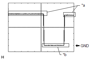
(1) Waveform
|
*a |
Steering Lock Motor not Operating |
|
*b |
Steering Lock Motor Operating |
|
Item |
Content |
|---|---|
|
Tester Connection |
F78-3 (IGEI) - F78-1 (GND) |
|
Tool Setting |
2 V/DIV., 200 ms./DIV. |
|
Vehicle Condition |
Steering lock motor not operating → Operating → Not operating |
 Problem Symptoms Table
PROBLEM SYMPTOMS TABLE
HINT:
Use the table below to help determine the cause of problem symptoms.
If multiple suspected areas are listed, the potential causes of the symptoms
are lis ...
 Diagnosis System
DIAGNOSIS SYSTEM
DESCRIPTION
(a) The steering lock ECU (steering lock actuator or upper bracket assembly)
stores DTCs when a malfunction occurs in the system. These DTCs can be confirmed
by usin ...
Other materials:
Toyota CH-R Service Manual > Tire Pressure Warning System: Operation Check
OPERATION CHECK
CHECK TIRE PRESSURE WARNING SYSTEM FUNCTION
(a) Using the Data List, check that the current tire pressure is normal.
Click here
(1) Slowly reduce the tire pressure of the front or rear tires and check that
the tire pressure on the Data List changes.
(2) Further reduce the ...
Toyota CH-R Service Manual > Cellular Communication: Dcm(telematics Transceiver)
Components
COMPONENTS
ILLUSTRATION
*1
DCM (TELEMATICS TRANSCEIVER)
-
-
N*m (kgf*cm, ft.*lbf): Specified torque
-
-
Removal
REMOVAL
CAUTION / NOTICE / HINT
The necessary procedures (adjus ...
Toyota C-HR (AX20) 2023-2026 Owner's Manual
Toyota CH-R Owners Manual
- For safety and security
- Instrument cluster
- Operation of each component
- Driving
- Interior features
- Maintenance and care
- When trouble arises
- Vehicle specifications
- For owners
Toyota CH-R Service Manual
- Introduction
- Maintenance
- Audio / Video
- Cellular Communication
- Navigation / Multi Info Display
- Park Assist / Monitoring
- Brake (front)
- Brake (rear)
- Brake Control / Dynamic Control Systems
- Brake System (other)
- Parking Brake
- Axle And Differential
- Drive Shaft / Propeller Shaft
- K114 Cvt
- 3zr-fae Battery / Charging
- Networking
- Power Distribution
- Power Assist Systems
- Steering Column
- Steering Gear / Linkage
- Alignment / Handling Diagnosis
- Front Suspension
- Rear Suspension
- Tire / Wheel
- Tire Pressure Monitoring
- Door / Hatch
- Exterior Panels / Trim
- Horn
- Lighting (ext)
- Mirror (ext)
- Window / Glass
- Wiper / Washer
- Door Lock
- Heating / Air Conditioning
- Interior Panels / Trim
- Lighting (int)
- Meter / Gauge / Display
- Mirror (int)
- Power Outlets (int)
- Pre-collision
- Seat
- Seat Belt
- Supplemental Restraint Systems
- Theft Deterrent / Keyless Entry

0.0093