Toyota CH-R Service Manual: Installation
INSTALLATION
PROCEDURE
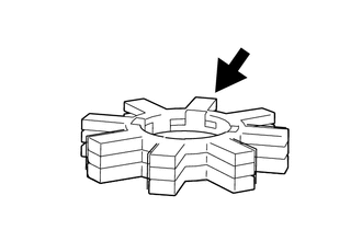
1. INSTALL ELECTRIC POWER STEERING MOTOR SHAFT DAMPER
.png) |
Grease |
(a) Apply grease to a new electric power steering motor shaft damper.
NOTICE:
First wipe off the existing grease from the serrated part, and then apply the dedicated grease supplied with a new power steering ECU assembly or electric power steering column sub-assembly.
(b) Install the electric power steering motor shaft damper to the electric power steering column sub-assembly.
2. INSTALL POWER STEERING ECU ASSEMBLY
NOTICE:
- Do not drop the power steering ECU assembly, strike it with tools or subject it to impacts.
- If the power steering ECU assembly is subjected to an impact, replace it with a new one.
- Do not pull the wire harness of the electric power steering column sub-assembly.
- Do not allow any moisture to come into contact with the power steering ECU assembly.
- Do not loosen any bolts not mentioned in the procedure.
- Do not allow any foreign matter to contaminate the power steering ECU assembly.
(a) for Type A:
(1) Using a T40 "TORX" socket wrench, temporarily install the power steering ECU assembly to the electric power steering column subassembly with the 2 screws.
NOTICE:
When temporarily installing the 2 screws to the power steering ECU assembly, do not tighten them all the way down.
(b) for Type B:
(1) Temporarily install the power steering ECU assembly to the electric power steering column sub-assembly with the 2 bolts.
NOTICE:
When temporarily installing the 2 bolts to the power steering ECU assembly, do not tighten them all the way down.
|
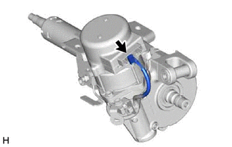
(c) Install 2 service nuts to the steering main shaft. Recommended Service Nut: Thread Diameter 12.0 mm (0.472 in.) Thread Pitch 1.25 mm (0.0492 in.) |
|
(d) Simultaneously rotate the service nut that was installed first counterclockwise and rotate the service nut that was installed second clockwise to lock them.
NOTICE:
Do not apply excessive torque to the service nuts by using a tool such as an impact wrench.
HINT:
The service nuts are used for turning the steering main shaft during inspection of the steering main shaft rotating torque.
Remove the service nuts after performing this inspection.
|
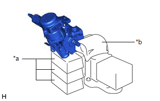
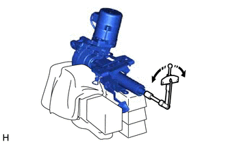
(e) Secure the steering column assembly in a vise using aluminum plates, cloths and wooden blocks. NOTICE:
|
|
|
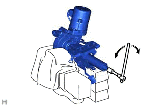
(f) Rotate the steering main shaft 180 degrees counterclockwise and then 180 degrees clockwise at a speed of 60 rpm, and repeat 2 to 3 times to center the axis of the power steering ECU assembly. [*1] |
|
(g) for Type A:
(1) Using a T40 "TORX" socket wrench, tighten the 2 screws. [*2]
Torque:
18.5 N·m {189 kgf·cm, 14 ft·lbf}
(h) for Type B:
(1) Tighten the 2 bolts. [*2]
Torque:
18.5 N·m {189 kgf·cm, 14 ft·lbf}
|
(i) Using a torque wrench, measure the turning torque of the steering main shaft. Preload: 1.2 to 2.4 N*m (13 to 24 kgf*cm, 11 to 21 in.*lbf) NOTICE: Ensure that there is no abnormal resistance during rotation. If the turning torque is not as specified, loosen the 2 bolts and repeat steps [*1] and [*2] to recenter the axis of the power steering ECU assembly. |
|
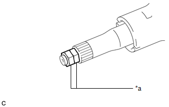
(j) Remove the 2 service nuts.
|
(k) Connect the connector. |
|
3. INSTALL STEERING COLUMN ASSEMBLY
Click here
.gif)
4. TORQUE SENSOR ZERO POINT CALIBRATION
Click here
5. ASSIST MAP WRITING
Click here
 Components
COMPONENTS
ILLUSTRATION
*1
ELECTRIC POWER STEERING MOTOR SHAFT DAMPER
*2
POWER STEERING ECU ASSEMBLY
*3
ELECTRIC POWER STEER ...
 Removal
REMOVAL
CAUTION / NOTICE / HINT
The necessary procedures (adjustment, calibration, initialization, or registration)
that must be performed after parts are removed, installed, or replaced during th ...
Other materials:
Toyota CH-R Service Manual > Electric Parking Brake System: Diagnostic Trouble Code Chart
DIAGNOSTIC TROUBLE CODE CHART
ELECTRIC PARKING BRAKE SYSTEM
DTC No.
Detection Item
Memory
Note
Link
C13A5
Electric Current of Motor
DTC stored
An electric parking brake system malfunction is di ...
Toyota CH-R Service Manual > Automatic Headlight Beam Level Control System: Headlight Beam Level Control Motor LH Malfunction (B2417,B2418)
DESCRIPTION
The headlight unit (headlight leveling motor) receives a signal from the headlight
control ECU sub-assembly to operate. The headlight control ECU sub-assembly receives
a signal indicating the operating conditions of the headlight unit (headlight leveling
motor).
DTC No ...
Toyota C-HR (AX20) 2023-2026 Owner's Manual
Toyota CH-R Owners Manual
- For safety and security
- Instrument cluster
- Operation of each component
- Driving
- Interior features
- Maintenance and care
- When trouble arises
- Vehicle specifications
- For owners
Toyota CH-R Service Manual
- Introduction
- Maintenance
- Audio / Video
- Cellular Communication
- Navigation / Multi Info Display
- Park Assist / Monitoring
- Brake (front)
- Brake (rear)
- Brake Control / Dynamic Control Systems
- Brake System (other)
- Parking Brake
- Axle And Differential
- Drive Shaft / Propeller Shaft
- K114 Cvt
- 3zr-fae Battery / Charging
- Networking
- Power Distribution
- Power Assist Systems
- Steering Column
- Steering Gear / Linkage
- Alignment / Handling Diagnosis
- Front Suspension
- Rear Suspension
- Tire / Wheel
- Tire Pressure Monitoring
- Door / Hatch
- Exterior Panels / Trim
- Horn
- Lighting (ext)
- Mirror (ext)
- Window / Glass
- Wiper / Washer
- Door Lock
- Heating / Air Conditioning
- Interior Panels / Trim
- Lighting (int)
- Meter / Gauge / Display
- Mirror (int)
- Power Outlets (int)
- Pre-collision
- Seat
- Seat Belt
- Supplemental Restraint Systems
- Theft Deterrent / Keyless Entry

0.0081