Toyota CH-R Service Manual: Removal
REMOVAL
CAUTION / NOTICE / HINT
The necessary procedures (adjustment, calibration, initialization, or registration) that must be performed after parts are removed, installed, or replaced during the power steering ECU assembly removal/installation are shown below.
Necessary Procedure After Parts Removed/Installed/Replaced|
Replacement Part or Procedure |
Necessary Procedures |
Effects / Inoperative when not performed |
Link |
|---|---|---|---|
|
Disconnect cable from negative battery terminal |
Initialize back door lock |
Power door lock control system |
|
|
Memorize steering angle neutral point |
Lane departure alert system (w/ Steering Control) |
|
|
|
Pre-collision system |
|||
|
Power steering ECU assembly |
|
|
|
PROCEDURE
1. REMOVE STEERING COLUMN ASSEMBLY
Click here
.gif)
2. REMOVE POWER STEERING ECU ASSEMBLY
NOTICE:
- Do not drop the power steering ECU assembly, strike it with tools or subject it to impacts.
- If the power steering ECU assembly is subjected to an impact, replace it with a new one.
- Do not pull the wire harness of the electric power steering column sub-assembly.
- Do not allow any moisture to come into contact with the power steering ECU assembly.
- Do not loosen any bolts not mentioned in the procedure.
- Do not allow any foreign matter to contaminate the power steering ECU assembly.
|
(a) Disconnect the connector. |
|
.png)
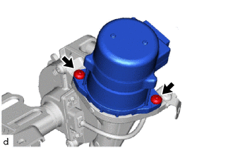
(b) for Type A:
|
(1) Using a T40 "TORX" socket wrench, remove the 2 screws and power steering ECU assembly from the electric power steering column sub-assembly. |
|
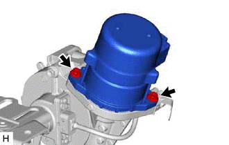
(c) for Type B:
|
(1) Remove the 2 bolts and power steering ECU assembly from the electric power steering column sub-assembly. |
|
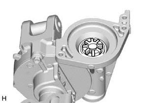
3. REMOVE ELECTRIC POWER STEERING MOTOR SHAFT DAMPER
|
(a) Remove the electric power steering motor shaft damper from the electric power steering column sub-assembly. |
|
 Installation
INSTALLATION
PROCEDURE
1. INSTALL ELECTRIC POWER STEERING MOTOR SHAFT DAMPER
Grease
(a) Apply grease to a new electric power steering motor shaft damper.
NOTICE:
F ...

Other materials:
Toyota CH-R Service Manual > Rear Axle Carrier: Installation
INSTALLATION
CAUTION / NOTICE / HINT
HINT:
Use the same procedure for the RH side and LH side.
The following procedure is for the LH side.
PROCEDURE
1. TEMPORARILY INSTALL REAR AXLE CARRIER SUB-ASSEMBLY
(a) Temporarily install the rear axle carrier sub-assembly to ...
Toyota CH-R Owners Manual > Adjusting the steering wheel and mirrors: Steering wheel
Adjustment procedure
1. Hold the steering wheel and push the lever down.
2. Adjust to the ideal position by moving the steering wheel horizontally and
vertically.
After adjustment, pull the lever up to secure the steering wheel.
Horn
To sound the horn, press on or close to the
mark.
...
Toyota C-HR (AX20) 2023-2026 Owner's Manual
Toyota CH-R Owners Manual
- For safety and security
- Instrument cluster
- Operation of each component
- Driving
- Interior features
- Maintenance and care
- When trouble arises
- Vehicle specifications
- For owners
Toyota CH-R Service Manual
- Introduction
- Maintenance
- Audio / Video
- Cellular Communication
- Navigation / Multi Info Display
- Park Assist / Monitoring
- Brake (front)
- Brake (rear)
- Brake Control / Dynamic Control Systems
- Brake System (other)
- Parking Brake
- Axle And Differential
- Drive Shaft / Propeller Shaft
- K114 Cvt
- 3zr-fae Battery / Charging
- Networking
- Power Distribution
- Power Assist Systems
- Steering Column
- Steering Gear / Linkage
- Alignment / Handling Diagnosis
- Front Suspension
- Rear Suspension
- Tire / Wheel
- Tire Pressure Monitoring
- Door / Hatch
- Exterior Panels / Trim
- Horn
- Lighting (ext)
- Mirror (ext)
- Window / Glass
- Wiper / Washer
- Door Lock
- Heating / Air Conditioning
- Interior Panels / Trim
- Lighting (int)
- Meter / Gauge / Display
- Mirror (int)
- Power Outlets (int)
- Pre-collision
- Seat
- Seat Belt
- Supplemental Restraint Systems
- Theft Deterrent / Keyless Entry

0.0068