Toyota CH-R Service Manual: Installation
INSTALLATION
PROCEDURE
1. INSTALL MAIN BODY ECU (MULTIPLEX NETWORK BODY ECU)
NOTICE:
- Make sure that the connecting surfaces are free of foreign matter.
- Do not touch the main body ECU (multiplex network body ECU) connector.
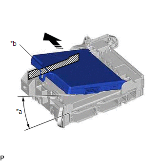
(a) Set the main body ECU (multiplex network body ECU) to the position where the guide of the main body ECU (multiplex network body ECU) contacts the housing sidewall of the instrument panel junction block assembly as shown in the illustration.
|
*a |
20° or more |
|
*b |
Housing Sidewall |
.png) |
Set in this Direction |
HINT:
Make sure to keep the angle at 20° or more as shown in the illustration.
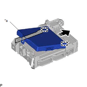
(b) Slide the main body ECU (multiplex network body ECU) along the housing sidewall as shown in the illustration and engage the guides.
|
*a |
Housing Sidewall |
|
|
Slide in this Direction |
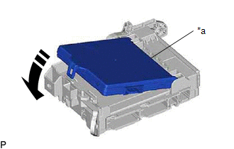
(c) While keeping the main body ECU (multiplex network body ECU) in contact with side A of the instrument panel junction block assembly (axis of rotation), lower it as shown in the illustration.
|
*a |
Side A |
|
|
Install in this Direction |
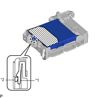
(d) Press the push area until the claw engages to install the main body ECU (multiplex network body ECU).
|
*1 |
Instrument Panel Junction Block Assembly |
|
*2 |
Main Body ECU (Multiplex Network Body ECU) |
.png) |
Push Area |
NOTICE:
- Make sure to press only the push area.
- Confirm the engagement of the main body ECU (multiplex network body ECU) and instrument panel junction block assembly by listening for the click sound of the lock engaging.
HINT:
If a click sound cannot be heard, visually check the engagement of the lock. The engagement can also be confirmed if the main body ECU (multiplex network body ECU) and instrument panel junction block assembly are flush.
|
(e) Engage the clamp to install the wiring harness clamp bracket. |
|
.png)
(f) Temporarily install the bolt.
HINT:
Do not fully tighten the bolt.
2. INSTALL INSTRUMENT PANEL JUNCTION BLOCK ASSEMBLY WITH MAIN BODY ECU
(a) Connect the 2 connectors and raise the lock levers to engage the claws and lock the connector as shown in the illustration.
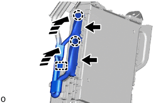
|
|
Install in this Direction |
NOTICE:
Be sure to connect the connector securely.
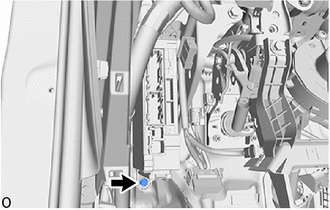
(b) Engage the clamp.
|
(c) Engage the clamp. |
|
.png)
|
(d) Engage the clamp to install the instrument panel junction block assembly with main body ECU. |
|
.png)
(e) Install the bolt and nut.
Torque:
8.0 N·m {82 kgf·cm, 71 in·lbf}
|
(f) Tighten the bolt. Torque: 8.0 N·m {82 kgf·cm, 71 in·lbf} |
|
(g) Connect the 2 connectors and raise the 2 lock levers to engage the claws and lock the connector as shown in the illustration.
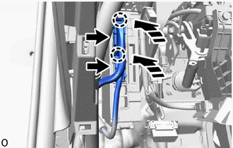
|
|
Install in this Direction |
NOTICE:
Be sure to connect the connector securely.
(h) Connect the 4 connectors.
|
(i) Engage the clamp. |
|
.png)
3. INSTALL NO. 3 INSTRUMENT PANEL TO COWL BRACE SUB-ASSEMBLY (except Cold Area Specification Vehicles)
Click here
.gif)
4. INSTALL NO. 3 INSTRUMENT PANEL TO COWL BRACE SUB-ASSEMBLY (for Cold Area Specification Vehicles)
Click here
5. INSTALL LOWER NO. 1 INSTRUMENT PANEL AIRBAG ASSEMBLY
Click here
6. CONNECT CABLE TO NEGATIVE BATTERY TERMINAL
NOTICE:
When disconnecting the cable, some systems need to be initialized after the cable is reconnected.
Click here
 Removal
REMOVAL
CAUTION / NOTICE / HINT
The necessary procedures (adjustment, calibration, initialization, or registration)
that must be performed after parts are removed and installed, or replaced during ...

Other materials:
Toyota CH-R Service Manual > Audio And Visual System(for Radio And Display Type): Certification ECU Vehicle Information Reading/Writing Process Malfunction (B15F7)
DESCRIPTION
This DTC is stored when items controlled by the certification ECU (smart key
ECU assembly) cannot be customized via the audio and visual system vehicle customization
screen.
HINT:
The certification ECU (smart key ECU assembly) controls the smart key system
related items that are ...
Toyota CH-R Service Manual > Wiper And Washer System: Terminals Of Ecu
TERMINALS OF ECU
CHECK WINDSHIELD WIPER RELAY ASSEMBLY (w/ Rain Sensor)
(a) Disconnect the F56 windshield wiper relay assembly connector.
(1) Measure the voltage and resistance on the wire harness side connector according
to the value(s) in the table below.
Terminal No.
(Symbol ...
Toyota C-HR (AX20) 2023-2026 Owner's Manual
Toyota CH-R Owners Manual
- For safety and security
- Instrument cluster
- Operation of each component
- Driving
- Interior features
- Maintenance and care
- When trouble arises
- Vehicle specifications
- For owners
Toyota CH-R Service Manual
- Introduction
- Maintenance
- Audio / Video
- Cellular Communication
- Navigation / Multi Info Display
- Park Assist / Monitoring
- Brake (front)
- Brake (rear)
- Brake Control / Dynamic Control Systems
- Brake System (other)
- Parking Brake
- Axle And Differential
- Drive Shaft / Propeller Shaft
- K114 Cvt
- 3zr-fae Battery / Charging
- Networking
- Power Distribution
- Power Assist Systems
- Steering Column
- Steering Gear / Linkage
- Alignment / Handling Diagnosis
- Front Suspension
- Rear Suspension
- Tire / Wheel
- Tire Pressure Monitoring
- Door / Hatch
- Exterior Panels / Trim
- Horn
- Lighting (ext)
- Mirror (ext)
- Window / Glass
- Wiper / Washer
- Door Lock
- Heating / Air Conditioning
- Interior Panels / Trim
- Lighting (int)
- Meter / Gauge / Display
- Mirror (int)
- Power Outlets (int)
- Pre-collision
- Seat
- Seat Belt
- Supplemental Restraint Systems
- Theft Deterrent / Keyless Entry

0.0106