Toyota CH-R Service Manual: Removal
REMOVAL
CAUTION / NOTICE / HINT
The necessary procedures (adjustment, calibration, initialization, or registration) that must be performed after parts are removed and installed, or replaced during the main body ECU (multiplex network body ECU) removal/installation are shown below.
Necessary Procedures After Parts Removed/Installed/Replaced|
Replaced Part or Performed Procedure |
Necessary Procedure |
Effect/Inoperative Function when Necessary Procedure not Performed |
Link |
|---|---|---|---|
|
Disconnect cable from negative battery terminal |
Initialize back door lock |
Power door lock control system |
|
|
Memorize steering angle neutral point |
Lane departure alert system (w/ Steering Control) |
|
|
|
Pre-collision system |
|||
|
Main body ECU (multiplex network body ECU) |
Perform code registration (Immobilizer system) |
|
w/ Smart Key System:
|
PROCEDURE
1. PRECAUTION
NOTICE:
After turning the ignition switch off, waiting time may be required before disconnecting the cable from the negative (-) battery terminal. Therefore, make sure to read the disconnecting the cable from the negative (-) battery terminal notices before proceeding with work.
Click here
.gif)
2. DISCONNECT CABLE FROM NEGATIVE BATTERY TERMINAL
NOTICE:
When disconnecting the cable, some systems need to be initialized after the cable is reconnected.
Click here
3. REMOVE LOWER NO. 1 INSTRUMENT PANEL AIRBAG ASSEMBLY
Click here
4. REMOVE NO. 3 INSTRUMENT PANEL TO COWL BRACE SUB-ASSEMBLY (except Cold Area Specification Vehicles)
Click here
5. REMOVE NO. 3 INSTRUMENT PANEL TO COWL BRACE SUB-ASSEMBLY (for Cold Area Specification Vehicles)
Click here
6. REMOVE INSTRUMENT PANEL JUNCTION BLOCK ASSEMBLY WITH MAIN BODY ECU
|
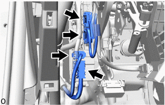
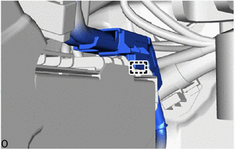
(a) Disengage the clamp. |
|
|
(b) Disconnect the 4 connectors. |
|
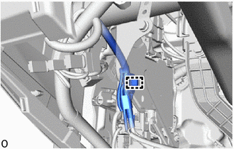
(c) Disengage the claws and pull down the lock levers to disconnect the 2 connectors as shown in the illustration.
.png) |
Remove in this Direction |
|
(d) Remove the bolt and nut. |
|
(e) Disengage the clamp.
(f) Pull out the instrument panel junction block assembly with main body ECU.
|
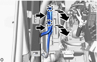
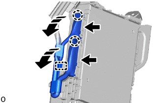
(g) Disengage the clamp. |
|
(h) Disengage the clamp.
|
|
Remove in this Direction |
(i) Disengage the claws and pull down the lock levers to disconnect the 2 connectors as shown in the illustration.
(j) Remove the instrument panel junction block assembly with main body ECU.
7. REMOVE MAIN BODY ECU (MULTIPLEX NETWORK BODY ECU)
|
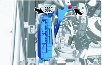
(a) Remove the bolt. |
|
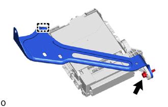
(b) Disengage the clamp to remove the wiring harness clamp bracket.
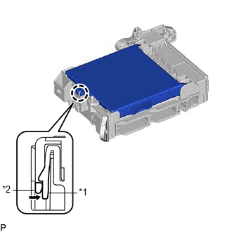
(c) Press the claw of the instrument panel junction block assembly as shown in the illustration to release the lock.
|
*1 |
Instrument Panel Junction Block Assembly |
|
*2 |
Main Body ECU (Multiplex Network Body ECU) |
.png) |
Push in this Direction |
(d) With the instrument panel junction block assembly lock released, insert a screwdriver with its tip wrapped in protective tape horizontally between the main body ECU (multiplex network body ECU) and the instrument panel junction block assembly.
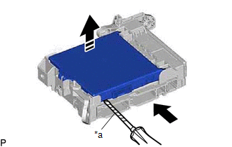
|
*a |
Protective Tape |
|
|
Insert in this Direction |
|
|
Remove in this Direction |
NOTICE:
- Use a screwdriver with a diameter between 5.0 mm (0.197 in.) and 6.3 mm (0.248 in.) and a length of approximately 90 mm (3.54 in.).
- Do not insert the screwdriver under the connector socket of the main body ECU (multiplex network body ECU).
(e) Using the screwdriver, carefully raise the main body ECU (multiplex network body ECU) to the position where the connector becomes disconnected.
NOTICE:
Do not twist the screwdriver to raise the main body ECU (multiplex network body ECU).
(f) Raise the main body ECU (multiplex network body ECU) as shown by the arrow (1), and then pull it out as shown by the arrow (2) in the illustration.
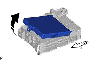
|
|
Remove in this Direction (1) |
.png) |
Remove in this Direction (2) |
NOTICE:
Do not touch the main body ECU (multiplex network body ECU) connector.
 Components
COMPONENTS
ILLUSTRATION
*A
except Cold Area Specification Vehicles
*B
for Cold Area Specification Vehicles
*1
INSTRUMENT PAN ...
 Installation
INSTALLATION
PROCEDURE
1. INSTALL MAIN BODY ECU (MULTIPLEX NETWORK BODY ECU)
NOTICE:
Make sure that the connecting surfaces are free of foreign matter.
Do not touch the main body EC ...
Other materials:
Toyota CH-R Service Manual > Navigation System: Vehicle Speed Signal Circuit between Navigation ECU and Combination Meter
DESCRIPTION
The navigation ECU receives a vehicle speed signal from the combination meter
assembly.
HINT:
A voltage of 12 V or 5 V is output from each ECU and then input to the
combination meter assembly. The signal is changed to a pulse signal at the
transistor in the combinati ...
Toyota CH-R Service Manual > Air Conditioning System(for Automatic Air Conditioning System With Side-mounted
Air Conditioner Pressure Sensor): Customize Parameters
CUSTOMIZE PARAMETERS
CUSTOMIZE AIR CONDITIONING SYSTEM
(a) Customizing with the Techstream.
NOTICE:
When the customer requests a change in a function, first make sure that
the function can be customized.
Be sure to make a note of the current settings before customizing.
Wh ...
Toyota C-HR (AX20) 2023-2026 Owner's Manual
Toyota CH-R Owners Manual
- For safety and security
- Instrument cluster
- Operation of each component
- Driving
- Interior features
- Maintenance and care
- When trouble arises
- Vehicle specifications
- For owners
Toyota CH-R Service Manual
- Introduction
- Maintenance
- Audio / Video
- Cellular Communication
- Navigation / Multi Info Display
- Park Assist / Monitoring
- Brake (front)
- Brake (rear)
- Brake Control / Dynamic Control Systems
- Brake System (other)
- Parking Brake
- Axle And Differential
- Drive Shaft / Propeller Shaft
- K114 Cvt
- 3zr-fae Battery / Charging
- Networking
- Power Distribution
- Power Assist Systems
- Steering Column
- Steering Gear / Linkage
- Alignment / Handling Diagnosis
- Front Suspension
- Rear Suspension
- Tire / Wheel
- Tire Pressure Monitoring
- Door / Hatch
- Exterior Panels / Trim
- Horn
- Lighting (ext)
- Mirror (ext)
- Window / Glass
- Wiper / Washer
- Door Lock
- Heating / Air Conditioning
- Interior Panels / Trim
- Lighting (int)
- Meter / Gauge / Display
- Mirror (int)
- Power Outlets (int)
- Pre-collision
- Seat
- Seat Belt
- Supplemental Restraint Systems
- Theft Deterrent / Keyless Entry

0.0119