Toyota CH-R Service Manual: Components
COMPONENTS
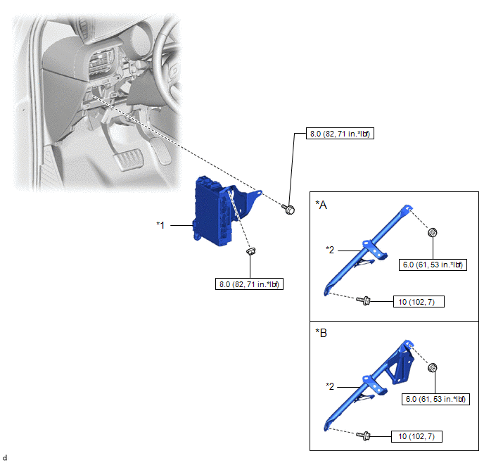
ILLUSTRATION
|
*A |
except Cold Area Specification Vehicles |
*B |
for Cold Area Specification Vehicles |
|
*1 |
INSTRUMENT PANEL JUNCTION BLOCK ASSEMBLY WITH MAIN BODY ECU |
*2 |
NO. 3 INSTRUMENT PANEL TO COWL BRACE SUB-ASSEMBLY |
.png) |
N*m (kgf*cm, ft.*lbf): Specified torque |
- |
- |
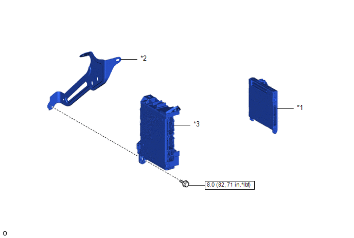
ILLUSTRATION
|
*1 |
MAIN BODY ECU (MULTIPLEX NETWORK BODY ECU) |
*2 |
WIRING HARNESS CLAMP BRACKET |
|
*3 |
INSTRUMENT PANEL JUNCTION BLOCK ASSEMBLY |
- |
- |
|
|
N*m (kgf*cm, ft.*lbf): Specified torque |
- |
- |
 Main Body Ecu
...
 Removal
REMOVAL
CAUTION / NOTICE / HINT
The necessary procedures (adjustment, calibration, initialization, or registration)
that must be performed after parts are removed and installed, or replaced during ...
Other materials:
Toyota CH-R Service Manual > Lighting System: Power Source Circuit
DESCRIPTION
When the ignition switch is ON or the operation conditions of the headlights
are met, the main body ECU (multiplex network body ECU) supplies power to the headlight
ECU sub-assemblies via the No. 1 integration relay.
When the ignition switch is ON, the main body ECU (multiplex netw ...
Toyota CH-R Service Manual > Audio And Visual System(for Radio And Display Type): GPS Antenna Connection Malfunction(short) (B15C0,B15C1)
DESCRIPTION
These DTCs are stored when a malfunction occurs in the navigation antenna assembly.
DTC No.
Detection Item
DTC Detection Condition
Trouble Area
B15C0
GPS Antenna Connection Malfunction(short)
Navigation ...
Toyota C-HR (AX20) 2023-2026 Owner's Manual
Toyota CH-R Owners Manual
- For safety and security
- Instrument cluster
- Operation of each component
- Driving
- Interior features
- Maintenance and care
- When trouble arises
- Vehicle specifications
- For owners
Toyota CH-R Service Manual
- Introduction
- Maintenance
- Audio / Video
- Cellular Communication
- Navigation / Multi Info Display
- Park Assist / Monitoring
- Brake (front)
- Brake (rear)
- Brake Control / Dynamic Control Systems
- Brake System (other)
- Parking Brake
- Axle And Differential
- Drive Shaft / Propeller Shaft
- K114 Cvt
- 3zr-fae Battery / Charging
- Networking
- Power Distribution
- Power Assist Systems
- Steering Column
- Steering Gear / Linkage
- Alignment / Handling Diagnosis
- Front Suspension
- Rear Suspension
- Tire / Wheel
- Tire Pressure Monitoring
- Door / Hatch
- Exterior Panels / Trim
- Horn
- Lighting (ext)
- Mirror (ext)
- Window / Glass
- Wiper / Washer
- Door Lock
- Heating / Air Conditioning
- Interior Panels / Trim
- Lighting (int)
- Meter / Gauge / Display
- Mirror (int)
- Power Outlets (int)
- Pre-collision
- Seat
- Seat Belt
- Supplemental Restraint Systems
- Theft Deterrent / Keyless Entry

0.0123