Toyota CH-R Service Manual: Torque Converter And Drive Plate
Inspection
INSPECTION
PROCEDURE
1. INSPECT TORQUE CONVERTER ASSEMBLY
|
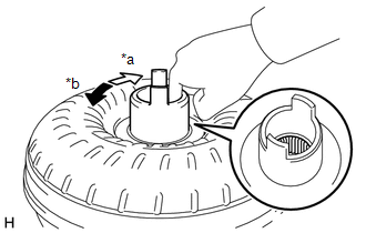
(a) Inspect the one-way clutch. (1) Press on the spline of the stator with a finger and rotate the spline. Check that the spline rotates smoothly when turned clockwise and rotates with difficulty when turned counterclockwise. If necessary, clean the torque converter assembly and recheck the one-way clutch. Replace the torque converter assembly if the one-way clutch still fails the inspection. |
|
|
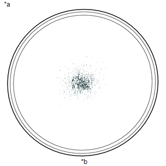
(b) Inspect the torque converter assembly. If any of the following problems are present, replace the torque converter assembly.
Malfunction:
HINT: The sample shows approximately 0.025 liters (0.026 US qts, 0.022 Imp. qts) of fluid in a petri dish, which has been taken from a torque converter assembly. |
|
(c) Replace the fluid in the torque converter assembly.
HINT:
If the fluid is discolored or has a foul odor, stir the fluid in the torque converter assembly and drain it before replacing the fluid.
|
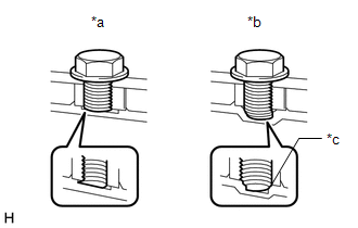
(d) Prevent deformation of the torque converter assembly and damage to the oil pump gear. NOTICE: Make sure that all of the bolts are the same length and that the specified bolts are used. HINT: If there is any damage to the tip of a bolt for the torque converter assembly or to the bottom of a bolt hole, replace the bolt and torque converter assembly. |
|
2. INSPECT DRIVE PLATE AND RING GEAR SUB-ASSEMBLY
(a) Check the drive plate for damage.
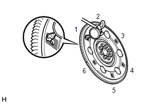
(b) Set up a dial indicator and measure the runout at the 6 areas on the drive plate surface that contact the torque converter assembly.
.png) |
Measurement Point |
Maximum runout:
0.30 mm (0.0118 in.)
If the runout is more than the maximum or the drive plate is damaged, replace the drive plate.
Click here
.gif)
 Shift Lever Knob
Components
COMPONENTS
ILLUSTRATION
*1
SHIFT LEVER CAP
*2
SHIFT LEVER KNOB SUB-ASSEMBLY
Removal
REMOVAL
PROCEDURE
1. REMOVE SHIFT LEVER ...

Other materials:
Toyota CH-R Service Manual > Seat Belt Warning System(w/o Occupant Classification System): How To Proceed With Troubleshooting
CAUTION / NOTICE / HINT
HINT:
Use the following procedure to troubleshoot the seat belt warning system.
*: Use the Techstream.
PROCEDURE
1.
VEHICLE BROUGHT TO WORKSHOP
NEXT
...
Toyota CH-R Service Manual > Steering Lock System: Power Source Control ECU Malfunction (B2782)
DESCRIPTION
The certification ECU (smart key ECU assembly) has a power source mode switching
function.
This DTC is stored when the IGEI input (the steering lock motor activation permission
signal) sent directly from the certification ECU (smart key ECU assembly) to the
steering lock ECU (ste ...
Toyota C-HR (AX20) 2023-2026 Owner's Manual
Toyota CH-R Owners Manual
- For safety and security
- Instrument cluster
- Operation of each component
- Driving
- Interior features
- Maintenance and care
- When trouble arises
- Vehicle specifications
- For owners
Toyota CH-R Service Manual
- Introduction
- Maintenance
- Audio / Video
- Cellular Communication
- Navigation / Multi Info Display
- Park Assist / Monitoring
- Brake (front)
- Brake (rear)
- Brake Control / Dynamic Control Systems
- Brake System (other)
- Parking Brake
- Axle And Differential
- Drive Shaft / Propeller Shaft
- K114 Cvt
- 3zr-fae Battery / Charging
- Networking
- Power Distribution
- Power Assist Systems
- Steering Column
- Steering Gear / Linkage
- Alignment / Handling Diagnosis
- Front Suspension
- Rear Suspension
- Tire / Wheel
- Tire Pressure Monitoring
- Door / Hatch
- Exterior Panels / Trim
- Horn
- Lighting (ext)
- Mirror (ext)
- Window / Glass
- Wiper / Washer
- Door Lock
- Heating / Air Conditioning
- Interior Panels / Trim
- Lighting (int)
- Meter / Gauge / Display
- Mirror (int)
- Power Outlets (int)
- Pre-collision
- Seat
- Seat Belt
- Supplemental Restraint Systems
- Theft Deterrent / Keyless Entry

0.0091