Toyota CH-R Service Manual: Components
COMPONENTS
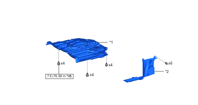
ILLUSTRATION
|
*1 |
NO. 1 ENGINE UNDER COVER |
*2 |
REAR ENGINE UNDER COVER LH |
.png) |
N*m (kgf*cm, ft.*lbf): Specified torque |
- |
- |
ILLUSTRATION
.png)
|
*1 |
AIR CLEANER CAP WITH AIR CLEANER HOSE |
*2 |
AIR CLEANER CASE SUB-ASSEMBLY |
|
*3 |
NO. 1 AIR CLEANER INLET |
*4 |
NO. 2 CYLINDER HEAD COVER |
|
*5 |
RADIATOR COVER |
*6 |
AIR CLEANER FILTER ELEMENT SUB-ASSEMBLY |
|
|
N*m (kgf*cm, ft.*lbf): Specified torque |
- |
- |
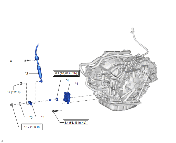
ILLUSTRATION
|
*1 |
PARK/NEUTRAL POSITION SWITCH |
*2 |
TRANSMISSION CONTROL CABLE ASSEMBLY |
|
*3 |
CONTROL SHAFT LEVER |
*4 |
LOCK PLATE |
|
*5 |
WASHER |
- |
- |
.png) |
Tightening torque for "Major areas involving basic vehicle performance such as moving/turning/stopping" : N*m (kgf*cm, ft.*lbf) |
|
N*m (kgf*cm, ft.*lbf): Specified torque |
|
● |
Non-reusable part |
- |
- |
 Precaution
PRECAUTION
IGNITION SWITCH EXPRESSIONS
(a) The type of ignition switch used on this model differs depending on the specifications
of the vehicle. The expressions listed in the table below are used ...
 On-vehicle Inspection
ON-VEHICLE INSPECTION
PROCEDURE
1. INSPECT PARK/NEUTRAL POSITION SWITCH OPERATION
(a) Apply the parking brake.
(b) Turn the ignition switch to ON.
(c) Depress the brake pedal and check that the e ...
Other materials:
Toyota CH-R Service Manual > Can Communication System: Front Camera Module Communication Stop Mode
DESCRIPTION
Detection Item
Symptom
Trouble Area
Front Camera Module Communication Stop Mode
Any of the following conditions are met:
Communication stop for "Front Camera Module" is indicated on
the "Comm ...
Toyota CH-R Service Manual > Automatic Light Control Sensor: Installation
INSTALLATION
PROCEDURE
1. INSTALL AUTOMATIC LIGHT CONTROL SENSOR
(a) Engage the claws to install the automatic light control sensor.
(b) Connect the connector.
2. INSTALL DEFROSTER NOZZLE ASSEMBLY
Click here
3. INSTALL INSTRUM ...
Toyota C-HR (AX20) 2023-2026 Owner's Manual
Toyota CH-R Owners Manual
- For safety and security
- Instrument cluster
- Operation of each component
- Driving
- Interior features
- Maintenance and care
- When trouble arises
- Vehicle specifications
- For owners
Toyota CH-R Service Manual
- Introduction
- Maintenance
- Audio / Video
- Cellular Communication
- Navigation / Multi Info Display
- Park Assist / Monitoring
- Brake (front)
- Brake (rear)
- Brake Control / Dynamic Control Systems
- Brake System (other)
- Parking Brake
- Axle And Differential
- Drive Shaft / Propeller Shaft
- K114 Cvt
- 3zr-fae Battery / Charging
- Networking
- Power Distribution
- Power Assist Systems
- Steering Column
- Steering Gear / Linkage
- Alignment / Handling Diagnosis
- Front Suspension
- Rear Suspension
- Tire / Wheel
- Tire Pressure Monitoring
- Door / Hatch
- Exterior Panels / Trim
- Horn
- Lighting (ext)
- Mirror (ext)
- Window / Glass
- Wiper / Washer
- Door Lock
- Heating / Air Conditioning
- Interior Panels / Trim
- Lighting (int)
- Meter / Gauge / Display
- Mirror (int)
- Power Outlets (int)
- Pre-collision
- Seat
- Seat Belt
- Supplemental Restraint Systems
- Theft Deterrent / Keyless Entry

0.0093