Toyota CH-R Service Manual: Removal
REMOVAL
CAUTION / NOTICE / HINT
The necessary procedures (adjustment, calibration, initialization, or registration) that must be performed after parts are removed, installed, or replaced during the oil cooler removal/installation are shown below.
Necessary Procedure After Parts Removed/Installed/Replaced|
Replacement Part or Procedure |
Necessary Procedure |
Effect/Inoperative when not Performed |
Link |
|---|---|---|---|
|
Replacement of CVT fluid |
ATF thermal degradation estimate reset |
The value of the Data List item "ATF Thermal Degradation Estimate" is not estimated correctly |
|
PROCEDURE
1. REMOVE NO. 1 ENGINE UNDER COVER
Click here
.gif)
2. REMOVE REAR ENGINE UNDER COVER LH
Click here
3. DRAIN CONTINUOUSLY VARIABLE TRANSAXLE FLUID
Click here
4. DRAIN ENGINE COOLANT
Click here
5. REMOVE NO. 2 CYLINDER HEAD COVER
Click here
6. REMOVE RADIATOR COVER
Click here
7. REMOVE NO. 1 AIR CLEANER INLET
Click here
8. REMOVE AIR CLEANER CAP WITH AIR CLEANER HOSE
Click here
9. REMOVE AIR CLEANER CASE SUB-ASSEMBLY
Click here
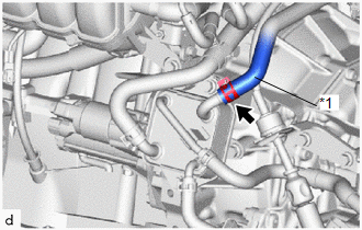
10. DISCONNECT NO. 3 WATER BY-PASS HOSE
|
(a) Slide the clip and disconnect the No. 3 water by-pass hose from the oil cooler. |
|
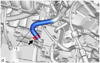
11. DISCONNECT NO. 5 WATER BY-PASS HOSE
|
(a) Slide the clip and disconnect the No. 5 water by-pass hose from the oil cooler. |
|
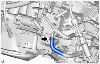
12. DISCONNECT NO. 1 TRANSMISSION OIL COOLER HOSE
|
(a) Slide the clip and disconnect the No. 1 transmission oil cooler hose from the oil cooler. |
|
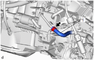
13. DISCONNECT NO. 2 TRANSMISSION OIL COOLER HOSE
|
(a) Slide the clip and disconnect the No. 2 transmission oil cooler hose from the oil cooler. |
|
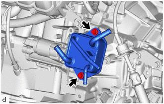
14. REMOVE OIL COOLER
|
(a) Remove the 2 bolts and oil cooler from the transmission oil cooler bracket. |
|
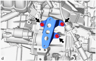
15. REMOVE TRANSMISSION OIL COOLER BRACKET
|
(a) Remove the 3 bolts and transmission oil cooler bracket from the continuously variable transaxle assembly. |
|
 Components
COMPONENTS
ILLUSTRATION
*1
NO. 1 ENGINE UNDER COVER
*2
REAR ENGINE UNDER COVER LH
N*m (kgf*cm, ft.*lbf): Specified torque
...
 Installation
INSTALLATION
PROCEDURE
1. INSTALL TRANSMISSION OIL COOLER BRACKET
(a) Install the transmission oil cooler bracket to the continuously variable
transaxle assembly with the 3 bolts in ...
Other materials:
Toyota CH-R Service Manual > Rear Door Courtesy Switch: Removal
REMOVAL
CAUTION / NOTICE / HINT
The necessary procedures (adjustment, calibration, initialization, or registration)
that must be performed after parts are removed, installed, or replaced during the
rear door courtesy switch removal/installation are shown below.
Necessary Procedures After Part ...
Toyota CH-R Service Manual > Id Code Box: Installation
INSTALLATION
CAUTION / NOTICE / HINT
NOTICE:
Before replacing the ID code box (immobiliser code ECU), refer to Registration.
Click here
PROCEDURE
1. INSTALL ID CODE BOX (IMMOBILISER CODE ECU)
(a) Engage the guides to install the ID code box (immobiliser code ECU) as shown
in the illustrat ...
Toyota C-HR (AX20) 2023-2026 Owner's Manual
Toyota CH-R Owners Manual
- For safety and security
- Instrument cluster
- Operation of each component
- Driving
- Interior features
- Maintenance and care
- When trouble arises
- Vehicle specifications
- For owners
Toyota CH-R Service Manual
- Introduction
- Maintenance
- Audio / Video
- Cellular Communication
- Navigation / Multi Info Display
- Park Assist / Monitoring
- Brake (front)
- Brake (rear)
- Brake Control / Dynamic Control Systems
- Brake System (other)
- Parking Brake
- Axle And Differential
- Drive Shaft / Propeller Shaft
- K114 Cvt
- 3zr-fae Battery / Charging
- Networking
- Power Distribution
- Power Assist Systems
- Steering Column
- Steering Gear / Linkage
- Alignment / Handling Diagnosis
- Front Suspension
- Rear Suspension
- Tire / Wheel
- Tire Pressure Monitoring
- Door / Hatch
- Exterior Panels / Trim
- Horn
- Lighting (ext)
- Mirror (ext)
- Window / Glass
- Wiper / Washer
- Door Lock
- Heating / Air Conditioning
- Interior Panels / Trim
- Lighting (int)
- Meter / Gauge / Display
- Mirror (int)
- Power Outlets (int)
- Pre-collision
- Seat
- Seat Belt
- Supplemental Restraint Systems
- Theft Deterrent / Keyless Entry

0.0089