Toyota CH-R Service Manual: Components
COMPONENTS
ILLUSTRATION
|
*1 |
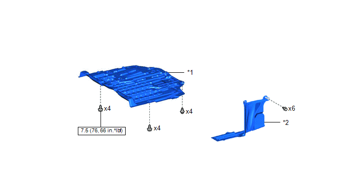
NO. 1 ENGINE UNDER COVER |
*2 |
REAR ENGINE UNDER COVER LH |
.png) |
N*m (kgf*cm, ft.*lbf): Specified torque |
- |
- |
ILLUSTRATION
|
*1 |
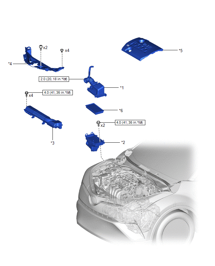
AIR CLEANER CAP WITH AIR CLEANER HOSE |
*2 |
AIR CLEANER CASE SUB-ASSEMBLY |
|
*3 |
NO. 1 AIR CLEANER INLET |
*4 |
NO. 2 CYLINDER HEAD COVER |
|
*5 |
RADIATOR COVER |
*6 |
AIR CLEANER FILTER ELEMENT SUB-ASSEMBLY |
|
|
N*m (kgf*cm, ft.*lbf): Specified torque |
- |
- |
ILLUSTRATION
|
*1 |
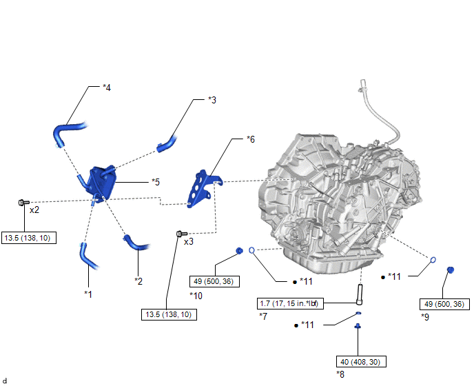
NO. 1 TRANSMISSION OIL COOLER HOSE |
*2 |
NO. 2 TRANSMISSION OIL COOLER HOSE |
|
*3 |
NO. 3 WATER BY-PASS HOSE |
*4 |
NO. 5 WATER BY-PASS HOSE |
|
*5 |
OIL COOLER |
*6 |
TRANSMISSION OIL COOLER BRACKET |
|
*7 |
NO. 1 TRANSMISSION OIL FILLER TUBE |
*8 |
OVERFLOW PLUG |
|
*9 |
REFILL PLUG |
*10 |
DRAIN PLUG |
|
*11 |
GASKET |
- |
- |
|
|
N*m (kgf*cm, ft.*lbf): Specified torque |
● |
Non-reusable part |
 Oil Cooler
...
 Removal
REMOVAL
CAUTION / NOTICE / HINT
The necessary procedures (adjustment, calibration, initialization, or registration)
that must be performed after parts are removed, installed, or replaced during th ...
Other materials:
Toyota CH-R Service Manual > Pre-collision System: Fail-safe Chart
FAIL-SAFE CHART
FAIL-SAFE FUNCTION
(a) When a malfunction occurs in the pre-collision system, a message will be
displayed on the multi-information display and the pre-collision system will be
disabled depending on the malfunction.
Warning Message
Cause
DTC No. ...
Toyota CH-R Service Manual > Rear Center Seat Outer Belt Assembly: Components
COMPONENTS
ILLUSTRATION
*1
REAR SEAT CENTER HEADREST ASSEMBLY
*2
REAR SEAT HEADREST ASSEMBLY
*3
REAR SEATBACK ASSEMBLY RH
-
-
Tightening torque for "Major areas involving ...
Toyota C-HR (AX20) 2023-2026 Owner's Manual
Toyota CH-R Owners Manual
- For safety and security
- Instrument cluster
- Operation of each component
- Driving
- Interior features
- Maintenance and care
- When trouble arises
- Vehicle specifications
- For owners
Toyota CH-R Service Manual
- Introduction
- Maintenance
- Audio / Video
- Cellular Communication
- Navigation / Multi Info Display
- Park Assist / Monitoring
- Brake (front)
- Brake (rear)
- Brake Control / Dynamic Control Systems
- Brake System (other)
- Parking Brake
- Axle And Differential
- Drive Shaft / Propeller Shaft
- K114 Cvt
- 3zr-fae Battery / Charging
- Networking
- Power Distribution
- Power Assist Systems
- Steering Column
- Steering Gear / Linkage
- Alignment / Handling Diagnosis
- Front Suspension
- Rear Suspension
- Tire / Wheel
- Tire Pressure Monitoring
- Door / Hatch
- Exterior Panels / Trim
- Horn
- Lighting (ext)
- Mirror (ext)
- Window / Glass
- Wiper / Washer
- Door Lock
- Heating / Air Conditioning
- Interior Panels / Trim
- Lighting (int)
- Meter / Gauge / Display
- Mirror (int)
- Power Outlets (int)
- Pre-collision
- Seat
- Seat Belt
- Supplemental Restraint Systems
- Theft Deterrent / Keyless Entry

0.0092