Toyota CH-R Service Manual: Terminals Of Ecu
TERMINALS OF ECU
CHECK MULTIPLEX NETWORK MASTER SWITCH ASSEMBLY

(a) Disconnect the J6 multiplex network master switch assembly connector.
(b) Measure the voltage and resistance according to the value(s) in the table below.
HINT:
Measure the values on the wire harness side with the connector disconnected.
|
Terminal No. (Symbol) |
Wiring Color |
Terminal Description |
Condition |
Specified Condition |
|---|---|---|---|---|
|
J6-11 (B) - J6-12 (GND) |
B - W-B |
Power supply |
Always |
11 to 14 V |
|
J6-12 (GND) - Body ground |
W-B - Body ground |
Ground |
Always |
Below 1 Ω |
(c) Reconnect the J6 multiplex network master switch assembly connector.
(d) Measure the voltage according to the value(s) in the table below.
|
Terminal No. (Symbol) |
Wiring Color |
Terminal Description |
Condition |
Specified Condition |
|---|---|---|---|---|
|
J6-15 (DOWN) - J6-12 (GND) |
Y - W-B |
Power window motor DOWN output |
Ignition switch ON, driver door power window regulator switch not pushed or pulled |
11 to 14 V |
|
J6-15 (DOWN) - J6-12 (GND) |
Y - W-B |
Power window motor DOWN output |
Ignition switch ON, driver door power window moving, driver door power window regulator switch pushed halfway down (Manual operation) |
Below 1 V |
|
J6-20 (UP) - J6-12 (GND) |
V - W-B |
Power window motor UP output |
Ignition switch ON, driver door power window regulator switch not pushed or pulled |
11 to 14 V |
|
J6-20 (UP) - J6-12 (GND) |
V - W-B |
Power window motor UP output |
Ignition switch ON, driver door power window moving, driver door power window regulator switch pulled halfway up (Manual operation) |
Below 1 V |
CHECK POWER WINDOW REGULATOR SWITCH ASSEMBLY

(a) Disconnect the I10 power window regulator switch assembly connector.
(b) Measure the resistance according to the value(s) in the table below.
HINT:
Measure the values on the wire harness side with the connector disconnected.
|
Terminal No. (Symbol) |
Wiring Color |
Terminal Description |
Condition |
Specified Condition |
|---|---|---|---|---|
|
I10-7 (GND) - Body ground |
W-B - Body ground |
Ground |
Always |
Below 1 Ω |
(c) Reconnect the I10 power window regulator switch assembly connector.
(d) Measure the voltage according to the value(s) in the table below.
|
Terminal No. (Symbol) |
Wiring Color |
Terminal Description |
Condition |
Specified Condition |
|---|---|---|---|---|
|
I10-2 (LED) - I10-7 (GND) |
R - W-B |
LED illumination signal |
Headlight dimmer switch is in the tail position |
11 to 14 V |
|
I10-2 (LED) - I10-7 (GND) |
R - W-B |
LED illumination signal |
Headlight dimmer switch is not in the tail position |
Below 1 V |
|
I10-5 (UP) - I10-7 (GND) |
V - W-B |
Power window motor UP output |
Ignition switch ON, power window regulator switch assembly not pushed or pulled |
11 to 14 V |
|
I10-5 (UP) - I10-7 (GND) |
V - W-B |
Power window motor UP output |
Ignition switch ON, front passenger door power window moving, power window regulator switch assembly pulled halfway up (Manual operation) |
Below 1 V |
|
I10-5 (UP) - I10-7 (GND) |
V - W-B |
Power window motor UP output |
Ignition switch ON, front passenger door power window fully open |
11 to 14 V |
|
I10-5 (UP) - I10-7 (GND) |
V - W-B |
Power window motor UP output |
Ignition switch ON, front passenger door power window moving, power window regulator switch assembly fully pulled up (Auto operation) |
Below 1 V |
|
I10-5 (UP) - I10-7 (GND) |
V - W-B |
Power window motor UP output |
Ignition switch ON, front passenger door power window fully closed |
11 to 14 V |
|
I10-4 (DOWN) - I10-7 (GND) |
Y - W-B |
Power window motor DOWN output |
Ignition switch ON, power window regulator switch assembly not pushed or pulled |
11 to 14 V |
|
I10-4 (DOWN) - I10-7 (GND) |
Y - W-B |
Power window motor DOWN output |
Ignition switch ON, front passenger door power window moving, power window regulator switch assembly pushed halfway down (Manual operation) |
Below 1 V |
|
I10-4 (DOWN) - I10-7 (GND) |
Y - W-B |
Power window motor DOWN output |
Ignition switch ON, front passenger door power window fully closed |
11 to 14 V |
|
I10-4 (DOWN) - I10-7 (GND) |
Y - W-B |
Power window motor DOWN output |
Ignition switch ON, front passenger door power window moving, power window regulator switch assembly fully pushed down (Auto operation) |
Below 1 V |
|
I10-4 (DOWN) - I10-7 (GND) |
Y - W-B |
Power window motor DOWN output |
Ignition switch ON, front passenger door power window fully open |
11 to 14 V |
|
I10-8 (AUTO) - I10-7 (GND) |
B - W-B |
Power window motor AUTO UP output |
Ignition switch ON, front passenger door power window fully open |
11 to 14 V |
|
I10-8 (AUTO) - I10-7 (GND) |
B - W-B |
Power window motor AUTO UP output |
Ignition switch ON, front passenger door power window moving, power window regulator switch assembly fully pulled up (Auto operation) |
Below 1 V |
|
I10-8 (AUTO) - I10-7 (GND) |
B - W-B |
Power window motor AUTO UP output |
Ignition switch ON, front passenger door power window fully closed |
11 to 14 V |
|
I10-8 (AUTO) - I10-7 (GND) |
B - W-B |
Power window motor AUTO DOWN output |
Ignition switch ON, front passenger door power window fully closed |
11 to 14 V |
|
I10-8 (AUTO) - I10-7 (GND) |
B - W-B |
Power window motor AUTO DOWN output |
Ignition switch ON, front passenger door power window moving, power window regulator switch assembly fully pushed down (Auto operation) |
Below 1 V |
|
I10-8 (AUTO) - I10-7 (GND) |
B - W-B |
Power window motor AUTO DOWN output |
Ignition switch ON, front passenger door power window fully open |
11 to 14 V |
CHECK REAR POWER WINDOW REGULATOR SWITCH ASSEMBLY (FOR LH DOOR)

(a) Disconnect the L3 rear power window regulator switch assembly (for LH door) connector.
(b) Measure the resistance according to the value(s) in the table below.
HINT:
Measure the values on the wire harness side with the connector disconnected.
|
Terminal No. (Symbol) |
Wiring Color |
Terminal Description |
Condition |
Specified Condition |
|---|---|---|---|---|
|
L3-7 (GND) - Body ground |
W-B - Body ground |
Ground |
Always |
Below 1 Ω |
(c) Reconnect the L3 rear power window regulator switch assembly (for LH door) connector.
(d) Measure the voltage according to the value(s) in the table below.
|
Terminal No. (Symbol) |
Wiring Color |
Terminal Description |
Condition |
Specified Condition |
|---|---|---|---|---|
|
L3-2 (LED) - L3-7 (GND) |
Y - W-B |
LED illumination signal |
Headlight dimmer switch is in the tail position |
11 to 14 V |
|
L3-2 (LED) - L3-7 (GND) |
Y - W-B |
LED illumination signal |
Headlight dimmer switch is not in the tail position |
Below 1 V |
|
L3-5 (UP) - L3-7 (GND) |
W - W-B |
Power window motor UP output |
Ignition switch ON, rear power window regulator switch assembly (for LH door) not pushed or pulled |
11 to 14 V |
|
L3-5 (UP) - L3-7 (GND) |
W - W-B |
Power window motor UP output |
Ignition switch ON, rear LH door power window moving, rear power window regulator switch assembly (for LH door) pulled halfway up (Manual operation) |
Below 1 V |
|
L3-5 (UP) - L3-7 (GND) |
W - W-B |
Power window motor UP output |
Ignition switch ON, rear LH door power window fully open |
11 to 14 V |
|
L3-5 (UP) - L3-7 (GND) |
W - W-B |
Power window motor UP output |
Ignition switch ON, rear LH door power window moving, rear power window regulator switch assembly (for LH door) fully pulled up (Auto operation) |
Below 1 V |
|
L3-5 (UP) - L3-7 (GND) |
W - W-B |
Power window motor UP output |
Ignition switch ON, rear LH door power window fully closed |
11 to 14 V |
|
L3-4 (DOWN) - L3-7 (GND) |
GR - W-B |
Power window motor DOWN output |
Ignition switch ON, rear power window regulator switch assembly (for LH door) not pushed or pulled |
11 to 14 V |
|
L3-4 (DOWN) - L3-7 (GND) |
GR - W-B |
Power window motor DOWN output |
Ignition switch ON, rear LH door power window moving, rear power window regulator switch assembly (for LH door) pushed halfway down (Manual operation) |
Below 1 V |
|
L3-4 (DOWN) - L3-7 (GND) |
GR - W-B |
Power window motor DOWN output |
Ignition switch ON, rear LH door power window fully closed |
11 to 14 V |
|
L3-4 (DOWN) - L3-7 (GND) |
GR - W-B |
Power window motor DOWN output |
Ignition switch ON, rear LH door power window moving, rear power window regulator switch assembly (for LH door) fully pushed down (Auto operation) |
Below 1 V |
|
L3-4 (DOWN) - L3-7 (GND) |
GR - W-B |
Power window motor DOWN output |
Ignition switch ON, rear LH door power window fully open |
11 to 14 V |
|
L3-8 (AUTO) - L3-7 (GND) |
V - W-B |
Power window motor AUTO UP output |
Ignition switch ON, rear LH door power window fully open |
11 to 14 V |
|
L3-8 (AUTO) - L3-7 (GND) |
V - W-B |
Power window motor AUTO UP output |
Ignition switch ON, rear LH door power window moving, rear power window regulator switch assembly (for LH door) fully pulled up (Auto operation) |
Below 1 V |
|
L3-8 (AUTO) - L3-7 (GND) |
V - W-B |
Power window motor AUTO UP output |
Ignition switch ON, rear LH door power window fully closed |
11 to 14 V |
|
L3-8 (AUTO) - L3-7 (GND) |
V - W-B |
Power window motor AUTO DOWN output |
Ignition switch ON, rear LH door power window fully closed |
11 to 14 V |
|
L3-8 (AUTO) - L3-7 (GND) |
V - W-B |
Power window motor AUTO DOWN output |
Ignition switch ON, rear LH door power window moving, rear power window regulator switch assembly (for LH door) fully pushed down (Auto operation) |
Below 1 V |
|
L3-8 (AUTO) - L3-7 (GND) |
V - W-B |
Power window motor AUTO DOWN output |
Ignition switch ON, rear LH door power window fully open |
11 to 14 V |
CHECK REAR POWER WINDOW REGULATOR SWITCH ASSEMBLY (FOR RH DOOR)

(a) Disconnect the K3 rear power window regulator switch assembly (for RH door) connector.
(b) Measure the resistance according to the value(s) in the table below.
HINT:
Measure the values on the wire harness side with the connector disconnected.
|
Terminal No. (Symbol) |
Wiring Color |
Terminal Description |
Condition |
Specified Condition |
|---|---|---|---|---|
|
K3-7 (GND) - Body ground |
W-B - Body ground |
Ground |
Always |
Below 1 Ω |
(c) Reconnect the K3 rear power window regulator switch assembly (for RH door) connector.
(d) Measure the voltage according to the value(s) in the table below.
|
Terminal No. (Symbol) |
Wiring Color |
Terminal Description |
Condition |
Specified Condition |
|---|---|---|---|---|
|
K3-2 (LED) - K3-7 (GND) |
Y - W-B |
LED illumination signal |
Headlight dimmer switch is in the tail position |
11 to 14 V |
|
K3-2 (LED) - K3-7 (GND) |
Y - W-B |
LED illumination signal |
Headlight dimmer switch is not in the tail position |
Below 1 V |
|
K3-5 (UP) - K3-7 (GND) |
W - W-B |
Power window motor UP output |
Ignition switch ON, rear power window regulator switch assembly (for RH door) not pushed or pulled |
11 to 14 V |
|
K3-5 (UP) - K3-7 (GND) |
W - W-B |
Power window motor UP output |
Ignition switch ON, rear RH door power window moving, rear power window regulator switch assembly (for RH door) pulled halfway up (Manual operation) |
Below 1 V |
|
K3-5 (UP) - K3-7 (GND) |
W - W-B |
Power window motor UP output |
Ignition switch ON, rear RH door power window fully open |
11 to 14 V |
|
K3-5 (UP) - K3-7 (GND) |
W - W-B |
Power window motor UP output |
Ignition switch ON, rear RH door power window moving, rear power window regulator switch assembly (for RH door) fully pulled up (Auto operation) |
Below 1 V |
|
K3-5 (UP) - K3-7 (GND) |
W - W-B |
Power window motor UP output |
Ignition switch ON, rear RH door power window fully closed |
11 to 14 V |
|
K3-4 (DOWN) - K3-7 (GND) |
GR - W-B |
Power window motor DOWN output |
Ignition switch ON, rear power window regulator switch assembly (for RH door) not pushed or pulled |
11 to 14 V |
|
K3-4 (DOWN) - K3-7 (GND) |
GR - W-B |
Power window motor DOWN output |
Ignition switch ON, rear RH door power window moving, rear power window regulator switch assembly (for RH door) pushed halfway down (Manual operation) |
Below 1 V |
|
K3-4 (DOWN) - K3-7 (GND) |
GR - W-B |
Power window motor DOWN output |
Ignition switch ON, rear RH door power window fully closed |
11 to 14 V |
|
K3-4 (DOWN) - K3-7 (GND) |
GR - W-B |
Power window motor DOWN output |
Ignition switch ON, rear RH door power window moving, rear power window regulator switch assembly (for RH door) fully pushed down (Auto operation) |
Below 1 V |
|
K3-4 (DOWN) - K3-7 (GND) |
GR - W-B |
Power window motor DOWN output |
Ignition switch ON, rear RH door power window fully open |
11 to 14 V |
|
K3-8 (AUTO) - K3-7 (GND) |
V - W-B |
Power window motor AUTO UP output |
Ignition switch ON, rear RH door power window fully open |
11 to 14 V |
|
K3-8 (AUTO) - K3-7 (GND) |
V - W-B |
Power window motor AUTO UP output |
Ignition switch ON, rear RH door power window moving, rear power window regulator switch assembly (for RH door) fully pulled up (Auto operation) |
Below 1 V |
|
K3-8 (AUTO) - K3-7 (GND) |
V - W-B |
Power window motor AUTO UP output |
Ignition switch ON, rear RH door power window fully closed |
11 to 14 V |
|
K3-8 (AUTO) - K3-7 (GND) |
V - W-B |
Power window motor AUTO DOWN output |
Ignition switch ON, rear RH door power window fully closed |
11 to 14 V |
|
K3-8 (AUTO) - K3-7 (GND) |
V - W-B |
Power window motor AUTO DOWN output |
Ignition switch ON, rear RH door power window moving, rear power window regulator switch assembly (for RH door) fully pushed down (Auto operation) |
Below 1 V |
|
K3-8 (AUTO) - K3-7 (GND) |
V - W-B |
Power window motor AUTO DOWN output |
Ignition switch ON, rear RH door power window fully open |
11 to 14 V |
CHECK POWER WINDOW REGULATOR MOTOR ASSEMBLY (FOR DRIVER DOOR)

(a) Disconnect the J2 power window regulator motor assembly (for driver door) connector.
(b) Measure the voltage and resistance according to the value(s) in the table below.
HINT:
Measure the values on the wire harness side with the connector disconnected.
|
Terminal No. (Symbol) |
Wiring Color |
Terminal Description |
Condition |
Specified Condition |
|---|---|---|---|---|
|
J2-1 (GND) - Body ground |
W-B - Body ground |
Ground |
Always |
Below 1 Ω |
|
J2-2 (B) - Body ground |
L - Body ground |
Power supply |
Always |
11 to 14 V |
(c) Reconnect the J2 power window regulator motor assembly (for driver door) connector.
(d) Measure the voltage according to the value(s) in the table below.
|
Terminal No. (Symbol) |
Wiring Color |
Terminal Description |
Condition |
Specified Condition |
|---|---|---|---|---|
|
J2-7 (DOWN) - J2-1 (GND) |
Y - W-B |
Power window motor DOWN input |
Ignition switch ON, multiplex network master switch assembly (driver door power window regulator switch) not pushed or pulled |
11 to 14 V |
|
J2-7 (DOWN) - J2-1 (GND) |
Y - W-B |
Power window motor DOWN input |
Ignition switch ON, driver door power window moving, multiplex network master switch assembly (driver door power window regulator switch) pushed halfway down (Manual operation) |
Below 1 V |
|
J2-7 (DOWN) - J2-1 (GND) |
Y - W-B |
Power window motor DOWN input |
Ignition switch ON, driver door power window fully closed |
11 to 14 V |
|
J2-7 (DOWN) - J2-1 (GND) |
Y - W-B |
Power window motor DOWN input |
Ignition switch ON, driver door power window moving, multiplex network master switch assembly (driver door power window regulator switch) fully pushed down (Auto operation) |
Below 1 V |
|
J2-7 (DOWN) - J2-1 (GND) |
Y - W-B |
Power window motor DOWN input |
Ignition switch ON, driver door power window fully open |
11 to 14 V |
|
J2-10 (UP) - J2-1 (GND) |
V - W-B |
Power window motor UP input |
Ignition switch ON, multiplex network master switch assembly (driver door power window regulator switch) not pushed or pulled |
11 to 14 V |
|
J2-10 (UP) - J2-1 (GND) |
V - W-B |
Power window motor UP input |
Ignition switch ON, driver door power window moving, multiplex network master switch assembly (driver door power window regulator switch) pulled halfway up (Manual operation) |
Below 1 V |
|
J2-10 (UP) - J2-1 (GND) |
V - W-B |
Power window motor UP input |
Ignition switch ON, multiplex network master switch assembly (driver door power window regulator switch) fully open |
11 to 14 V |
|
J2-10 (UP) - J2-1 (GND) |
V - W-B |
Power window motor UP input |
Ignition switch ON, driver door power window moving, multiplex network master switch assembly (driver door power window regulator switch) fully pulled up (Auto operation) |
Below 1 V |
|
J2-10 (UP) - J2-1 (GND) |
V - W-B |
Power window motor UP input |
Ignition switch ON, driver door power window fully closed |
11 to 14 V |
CHECK POWER WINDOW REGULATOR MOTOR ASSEMBLY (FOR FRONT PASSENGER DOOR)

(a) Disconnect the I2 power window regulator motor assembly (for front passenger door) connector.
(b) Measure the voltage and resistance according to the value(s) in the table below.
HINT:
Measure the values on the wire harness side with the connector disconnected.
|
Terminal No. (Symbol) |
Wiring Color |
Terminal Description |
Condition |
Specified Condition |
|---|---|---|---|---|
|
I2-1 (GND) - Body ground |
W-B - Body ground |
Ground |
Always |
Below 1 Ω |
|
I2-2 (B) - Body ground |
L - Body ground |
Power supply |
Always |
11 to 14 V |
(c) Reconnect the I2 power window regulator motor assembly (for front passenger door) connector.
(d) Measure the voltage according to the value(s) in the table below.
|
Terminal No. (Symbol) |
Wiring Color |
Terminal Description |
Condition |
Specified Condition |
|---|---|---|---|---|
|
I2-4 (AUTO) - I2-1 (GND) |
B - W-B |
Power window motor AUTO UP input |
Ignition switch ON, front passenger door power window fully open |
11 to 14 V |
|
I2-4 (AUTO) - I2-1 (GND) |
B - W-B |
Power window motor AUTO UP input |
Ignition switch ON, front passenger door power window moving, power window regulator switch assembly fully pulled up (Auto operation) |
Below 1 V |
|
I2-4 (AUTO) - I2-1 (GND) |
B - W-B |
Power window motor AUTO UP input |
Ignition switch ON, front passenger door power window fully closed |
11 to 14 V |
|
I2-4 (AUTO) - I2-1 (GND) |
B - W-B |
Power window motor AUTO DOWN input |
Ignition switch ON, front passenger door power window fully closed |
11 to 14 V |
|
I2-4 (AUTO) - I2-1 (GND) |
B - W-B |
Power window motor AUTO DOWN input |
Ignition switch ON, front passenger door power window moving, power window regulator switch assembly fully pushed down (Auto operation) |
Below 1 V |
|
I2-4 (AUTO) - I2-1 (GND) |
B - W-B |
Power window motor AUTO DOWN input |
Ignition switch ON, front passenger door power window fully open |
11 to 14 V |
|
I2-5 (LED) - I2-1 (GND) |
R - W-B |
LED illumination signal |
Headlight dimmer switch is in the tail position |
11 to 14 V |
|
I2-5 (LED) - I2-1 (GND) |
R - W-B |
LED illumination signal |
Headlight dimmer switch is not in the tail position |
Below 1 V |
|
I2-7 (DOWN) - I2-1 (GND) |
Y - W-B |
Power window motor DOWN input |
Ignition switch ON, power window regulator switch assembly not pushed or pulled |
11 to 14 V |
|
I2-7 (DOWN) - I2-1 (GND) |
Y - W-B |
Power window motor DOWN input |
Ignition switch ON, front passenger door power window moving, power window regulator switch assembly pushed halfway down (Manual operation) |
Below 1 V |
|
I2-7 (DOWN) - I2-1 (GND) |
Y - W-B |
Power window motor DOWN input |
Ignition switch ON, front passenger door power window fully closed |
11 to 14 V |
|
I2-7 (DOWN) - I2-1 (GND) |
Y - W-B |
Power window motor DOWN input |
Ignition switch ON, front passenger door power window moving, power window regulator switch assembly fully pushed down (Auto operation) |
Below 1 V |
|
I2-7 (DOWN) - I2-1 (GND) |
Y - W-B |
Power window motor DOWN input |
Ignition switch ON, front passenger door power window fully open |
11 to 14 V |
|
I2-10 (UP) - I2-1 (GND) |
V - W-B |
Power window motor UP input |
Ignition switch ON, power window regulator switch assembly not pushed or pulled |
11 to 14 V |
|
I2-10 (UP) - I2-1 (GND) |
V - W-B |
Power window motor UP input |
Ignition switch ON, front passenger door power window moving, power window regulator switch assembly pulled halfway up (Manual operation) |
Below 1 V |
|
I2-10 (UP) - I2-1 (GND) |
V - W-B |
Power window motor UP input |
Ignition switch ON, front passenger door power window fully open |
11 to 14 V |
|
I2-10 (UP) - I2-1 (GND) |
V - W-B |
Power window motor UP input |
Ignition switch ON, front passenger door power window moving, power window regulator switch assembly fully pulled up (Auto operation) |
Below 1 V |
|
I2-10 (UP) - I2-1 (GND) |
V - W-B |
Power window motor UP input |
Ignition switch ON, front passenger door power window fully closed |
11 to 14 V |
CHECK POWER WINDOW REGULATOR MOTOR ASSEMBLY (FOR REAR LH DOOR)

(a) Disconnect the L2 power window regulator motor assembly (for rear LH door) connector.
(b) Measure the voltage and resistance according to the value(s) in the table below.
HINT:
Measure the values on the wire harness side with the connector disconnected.
|
Terminal No. (Symbol) |
Wiring Color |
Terminal Description |
Condition |
Specified Condition |
|---|---|---|---|---|
|
L2-1 (GND) - Body ground |
W-B - Body ground |
Ground |
Always |
Below 1 Ω |
|
L2-2 (B) - Body ground |
R - Body ground |
Power supply |
Always |
11 to 14 V |
(c) Reconnect the L2 power window regulator motor assembly (for rear LH door) connector.
(d) Measure the voltage according to the value(s) in the table below.
|
Terminal No. (Symbol) |
Wiring Color |
Terminal Description |
Condition |
Specified Condition |
|---|---|---|---|---|
|
L2-4 (AUTO) - L2-1 (GND) |
V - W-B |
Power window motor AUTO UP input |
Ignition switch ON, rear LH door power window fully open |
11 to 14 V |
|
L2-4 (AUTO) - L2-1 (GND) |
V - W-B |
Power window motor AUTO UP input |
Ignition switch ON, rear LH door power window moving, rear power window regulator switch assembly (for LH door) fully pulled up (Auto operation) |
Below 1 V |
|
L2-4 (AUTO) - L2-1 (GND) |
V - W-B |
Power window motor AUTO UP input |
Ignition switch ON, rear LH door power window fully closed |
11 to 14 V |
|
L2-4 (AUTO) - L2-1 (GND) |
V - W-B |
Power window motor AUTO DOWN input |
Ignition switch ON, rear LH door power window fully closed |
11 to 14 V |
|
L2-4 (AUTO) - L2-1 (GND) |
V - W-B |
Power window motor AUTO DOWN input |
Ignition switch ON, rear LH door power window moving, rear power window regulator switch assembly (for LH door) fully pushed down (Auto operation) |
Below 1 V |
|
L2-4 (AUTO) - L2-1 (GND) |
V - W-B |
Power window motor AUTO DOWN input |
Ignition switch ON, rear LH door power window fully open |
11 to 14 V |
|
L2-5 (LED) - L2-1 (GND) |
Y - W-B |
LED illumination signal |
Headlight dimmer switch is in the tail position |
11 to 14 V |
|
L2-5 (LED) - L2-1 (GND) |
Y - W-B |
LED illumination signal |
Headlight dimmer switch is not in the tail position |
Below 1 V |
|
L2-7 (DOWN) - L2-1 (GND) |
GR - W-B |
Power window motor DOWN input |
Ignition switch ON, rear power window regulator switch assembly (for LH door) not pushed or pulled |
11 to 14 V |
|
L2-7 (DOWN) - L2-1 (GND) |
GR - W-B |
Power window motor DOWN input |
Ignition switch ON, rear LH door power window moving, rear power window regulator switch assembly (for LH door) pushed halfway down (Manual operation) |
Below 1 V |
|
L2-7 (DOWN) - L2-1 (GND) |
GR - W-B |
Power window motor DOWN input |
Ignition switch ON, rear LH door power window fully closed |
11 to 14 V |
|
L2-7 (DOWN) - L2-1 (GND) |
GR - W-B |
Power window motor DOWN input |
Ignition switch ON, rear LH door power window moving, rear power window regulator switch assembly (for LH door) fully pushed down (Auto operation) |
Below 1 V |
|
L2-7 (DOWN) - L2-1 (GND) |
GR - W-B |
Power window motor DOWN input |
Ignition switch ON, rear LH door power window fully open |
11 to 14 V |
|
L2-10 (UP) - L2-1 (GND) |
W - W-B |
Power window motor UP input |
Ignition switch ON, rear power window regulator switch assembly (for LH door) not pushed or pulled |
11 to 14 V |
|
L2-10 (UP) - L2-1 (GND) |
W - W-B |
Power window motor UP input |
Ignition switch ON, rear LH door power window moving, rear power window regulator switch assembly (for LH door) pulled halfway up (Manual operation) |
Below 1 V |
|
L2-10 (UP) - L2-1 (GND) |
W - W-B |
Power window motor UP input |
Ignition switch ON, rear LH door power window fully open |
11 to 14 V |
|
L2-10 (UP) - L2-1 (GND) |
W - W-B |
Power window motor UP input |
Ignition switch ON, rear LH door power window moving, rear power window regulator switch assembly (for LH door) fully pulled up (Auto operation) |
Below 1 V |
|
L2-10 (UP) - L2-1 (GND) |
W - W-B |
Power window motor UP input |
Ignition switch ON, rear LH door power window fully closed |
11 to 14 V |
CHECK POWER WINDOW REGULATOR MOTOR ASSEMBLY (FOR REAR RH DOOR)

(a) Disconnect the K2 power window regulator motor assembly (for rear RH door) connector.
(b) Measure the voltage and resistance according to the value(s) in the table below.
HINT:
Measure the values on the wire harness side with the connector disconnected.
|
Terminal No. (Symbol) |
Wiring Color |
Terminal Description |
Condition |
Specified Condition |
|---|---|---|---|---|
|
K2-1 (GND) - Body ground |
W-B - Body ground |
Ground |
Always |
Below 1 Ω |
|
K2-2 (B) - Body ground |
R - Body ground |
Power supply |
Always |
11 to 14 V |
(c) Reconnect the K2 power window regulator motor assembly (for rear RH door) connector.
(d) Measure the voltage according to the value(s) in the table below.
|
Terminal No. (Symbol) |
Wiring Color |
Terminal Description |
Condition |
Specified Condition |
|---|---|---|---|---|
|
K2-4 (AUTO) - K2-1 (GND) |
V - W-B |
Power window motor AUTO UP input |
Ignition switch ON, rear RH door power window fully open |
11 to 14 V |
|
K2-4 (AUTO) - K2-1 (GND) |
V - W-B |
Power window motor AUTO UP input |
Ignition switch ON, rear RH door power window moving, rear power window regulator switch assembly (for RH door) fully pulled up (Auto operation) |
Below 1 V |
|
K2-4 (AUTO) - K2-1 (GND) |
V - W-B |
Power window motor AUTO UP input |
Ignition switch ON, rear RH door power window fully closed |
11 to 14 V |
|
K2-4 (AUTO) - K2-1 (GND) |
V - W-B |
Power window motor AUTO DOWN input |
Ignition switch ON, rear RH door power window fully closed |
11 to 14 V |
|
K2-4 (AUTO) - K2-1 (GND) |
V - W-B |
Power window motor AUTO DOWN input |
Ignition switch ON, rear RH door power window moving, rear power window regulator switch assembly (for RH door) fully pushed down (Auto operation) |
Below 1 V |
|
K2-4 (AUTO) - K2-1 (GND) |
V - W-B |
Power window motor AUTO DOWN input |
Ignition switch ON, rear RH door power window fully open |
11 to 14 V |
|
K2-5 (LED) - K2-1 (GND) |
Y - W-B |
LED illumination signal |
Headlight dimmer switch is in the tail position |
11 to 14 V |
|
K2-5 (LED) - K2-1 (GND) |
Y - W-B |
LED illumination signal |
Headlight dimmer switch is not in the tail position |
Below 1 V |
|
K2-7 (DOWN) - K2-1 (GND) |
GR - W-B |
Power window motor DOWN input |
Ignition switch ON, rear power window regulator switch assembly (for RH door) not pushed or pulled |
11 to 14 V |
|
K2-7 (DOWN) - K2-1 (GND) |
GR - W-B |
Power window motor DOWN input |
Ignition switch ON, rear RH door power window moving, rear power window regulator switch assembly (for RH door) pushed halfway down (Manual operation) |
Below 1 V |
|
K2-7 (DOWN) - K2-1 (GND) |
GR - W-B |
Power window motor DOWN input |
Ignition switch ON, rear RH door power window fully closed |
11 to 14 V |
|
K2-7 (DOWN) - K2-1 (GND) |
GR - W-B |
Power window motor DOWN input |
Ignition switch ON, rear RH door power window moving, rear power window regulator switch assembly (for RH door) fully pushed down (Auto operation) |
Below 1 V |
|
K2-7 (DOWN) - K2-1 (GND) |
GR - W-B |
Power window motor DOWN input |
Ignition switch ON, rear RH door power window fully open |
11 to 14 V |
|
K2-10 (UP) - K2-1 (GND) |
W - W-B |
Power window motor UP input |
Ignition switch ON, rear power window regulator switch assembly (for RH door) not pushed or pulled |
11 to 14 V |
|
K2-10 (UP) - K2-1 (GND) |
W - W-B |
Power window motor UP input |
Ignition switch ON, rear RH door power window moving, rear power window regulator switch assembly (for RH door) pulled halfway up (Manual operation) |
Below 1 V |
|
K2-10 (UP) - K2-1 (GND) |
W - W-B |
Power window motor UP input |
Ignition switch ON, rear RH door power window fully open |
11 to 14 V |
|
K2-10 (UP) - K2-1 (GND) |
W - W-B |
Power window motor UP input |
Ignition switch ON, rear RH door power window moving, rear power window regulator switch assembly (for RH door) fully pulled up (Auto operation) |
Below 1 V |
|
K2-10 (UP) - K2-1 (GND) |
W - W-B |
Power window motor UP input |
Ignition switch ON, rear RH door power window fully closed |
11 to 14 V |
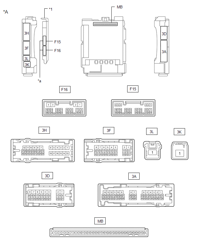
CHECK INSTRUMENT PANEL JUNCTION BLOCK ASSEMBLY AND MAIN BODY ECU (MULTIPLEX NETWORK BODY ECU)
|
*A |
Main Body ECU (Multiplex Network Body ECU) with 2 Connectors |
- |
- |
|
*1 |
Main Body ECU (Multiplex Network Body ECU) |
- |
- |
|
*a |
2 Connectors |
- |
- |
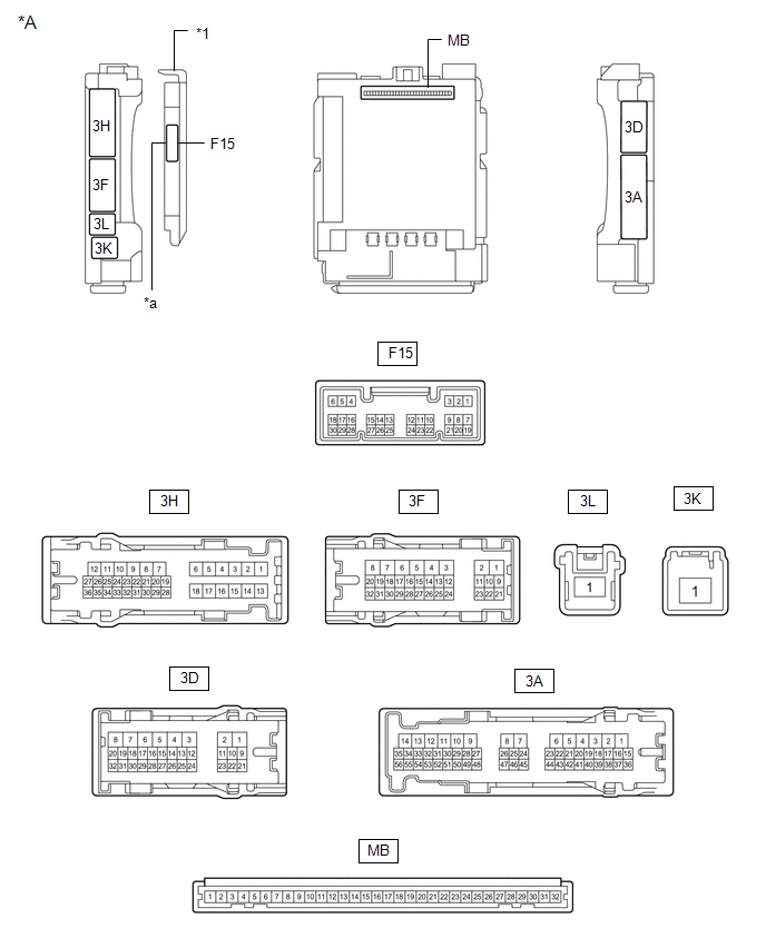
|
*A |
Main Body ECU (Multiplex Network Body ECU) with 1 Connector |
- |
- |
|
*1 |
Main Body ECU (Multiplex Network Body ECU) |
- |
- |
|
*a |
1 Connector |
- |
- |
(a) Remove the main body ECU (multiplex network body ECU) from the instrument panel junction block assembly.
Click here
.gif)
(b) Reconnect the instrument panel junction block assembly connectors.
(c) Measure the voltage and resistance according to the value(s) in the table below.
HINT:
Measure the values on the wire harness side with the connectors connected.
|
Terminal No. (Symbol) |
Wiring Color |
Terminal Description |
Condition |
Specified Condition |
|---|---|---|---|---|
|
MB-11 (GND1) - Body ground |
- |
Ground |
Always |
Below 1 Ω |
|
MB-31 (BECU) - Body ground |
- |
Battery power supply |
Always |
11 to 14 V |
|
MB-30 (ACC) - Body ground |
- |
ACC power supply |
Ignition switch ACC |
11 to 14 V |
|
MB-30 (ACC) - Body ground |
- |
ACC power supply |
Ignition switch off |
Below 1 V |
|
MB-32 (IG) - Body ground |
- |
IG power supply |
Ignition switch ON |
11 to 14 V |
|
MB-32 (IG) - Body ground |
- |
IG power supply |
Ignition switch off |
Below 1 V |
(d) Install the main body ECU (multiplex network body ECU) to the instrument panel junction block assembly.
Click here
(e) Measure the voltage and check for pulses according to the value(s) in the table below.
|
Terminal No. (Symbol) |
Wiring Color |
Terminal Description |
Condition |
Specified Condition |
|---|---|---|---|---|
|
F15-6 (FLCY) - Body ground |
R - Body ground |
Front door courtesy light switch (for LH) input |
Front door LH open |
Below 1 V |
|
F15-6 (FLCY) - Body ground |
R - Body ground |
Front door courtesy light switch (for LH) input |
Front door LH closed |
11 to 14 V |
|
F15-27 (FRCY) - Body ground |
BR - Body ground |
Front door courtesy light switch (for RH) input |
Front door RH open |
Below 1 V |
|
F15-27 (FRCY) - Body ground |
BR - Body ground |
Front door courtesy light switch (for RH) input |
Front door RH closed |
11 to 14 V |
|
F15-29 (L2) - Body ground |
G - Body ground |
Driver door key-linked lock input |
Driver door key cylinder turned to lock |
Below 1 V |
|
F15-29 (L2) - Body ground |
G - Body ground |
Driver door key-linked lock input |
Driver door key cylinder not turned |
Pulse generation |
|
F15-2 (UL3) - Body ground |
L - Body ground |
Driver door key-linked unlock input |
Driver door key cylinder turned to unlock |
Below 1 V |
|
F15-2 (UL3) - Body ground |
L - Body ground |
Driver door key-linked unlock input |
Driver door key cylinder not turned |
Pulse generation |
 Problem Symptoms Table
PROBLEM SYMPTOMS TABLE
NOTICE:
Before replacing the main body ECU (multiplex network body ECU), refer
to Registration.*1
Click here
*1: w/ Smart Key System
...
 Diagnosis System
DIAGNOSIS SYSTEM
DESCRIPTION
(a) Power window control system data and Diagnostic Trouble Codes (DTCs) can
be read through the vehicle Data Link Connector 3 (DLC3). When the system seems
to be ma ...
Other materials:
Toyota CH-R Service Manual > Steering Pad Switch: Inspection
INSPECTION
PROCEDURE
1. INSPECT STEERING PAD SWITCH ASSEMBLY
(a) Measure the resistance according to the value(s) in the table below.
*A
w/ Lane Departure Alert System
*B
w/ Voice Switch
*C
w/ Microphone
-
...
Toyota CH-R Service Manual > Toyota Entune System: GPS Mark is not Displayed
CAUTION / NOTICE / HINT
NOTICE:
Depending on the parts that are replaced during vehicle inspection or
maintenance, performing initialization, registration or calibration may
be needed. Refer to Precaution for Audio and Visual System.
Click here
The following may o ...
Toyota C-HR (AX20) 2023-2026 Owner's Manual
Toyota CH-R Owners Manual
- For safety and security
- Instrument cluster
- Operation of each component
- Driving
- Interior features
- Maintenance and care
- When trouble arises
- Vehicle specifications
- For owners
Toyota CH-R Service Manual
- Introduction
- Maintenance
- Audio / Video
- Cellular Communication
- Navigation / Multi Info Display
- Park Assist / Monitoring
- Brake (front)
- Brake (rear)
- Brake Control / Dynamic Control Systems
- Brake System (other)
- Parking Brake
- Axle And Differential
- Drive Shaft / Propeller Shaft
- K114 Cvt
- 3zr-fae Battery / Charging
- Networking
- Power Distribution
- Power Assist Systems
- Steering Column
- Steering Gear / Linkage
- Alignment / Handling Diagnosis
- Front Suspension
- Rear Suspension
- Tire / Wheel
- Tire Pressure Monitoring
- Door / Hatch
- Exterior Panels / Trim
- Horn
- Lighting (ext)
- Mirror (ext)
- Window / Glass
- Wiper / Washer
- Door Lock
- Heating / Air Conditioning
- Interior Panels / Trim
- Lighting (int)
- Meter / Gauge / Display
- Mirror (int)
- Power Outlets (int)
- Pre-collision
- Seat
- Seat Belt
- Supplemental Restraint Systems
- Theft Deterrent / Keyless Entry

0.0084