Toyota CH-R Service Manual: Installation
INSTALLATION
PROCEDURE
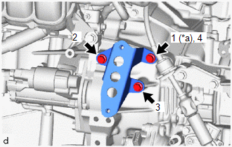
1. INSTALL TRANSMISSION OIL COOLER BRACKET
|
(a) Install the transmission oil cooler bracket to the continuously variable transaxle assembly with the 3 bolts in the order shown in the illustration. Torque: 13.5 N·m {138 kgf·cm, 10 ft·lbf} |
|
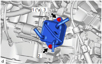
2. INSTALL OIL COOLER
|
(a) Install the oil cooler to the transmission oil cooler bracket with the 2 bolts in the order shown in the illustration. Torque: 13.5 N·m {138 kgf·cm, 10 ft·lbf} |
|
3. CONNECT NO. 1 TRANSMISSION OIL COOLER HOSE
(a) Connect the No. 1 transmission oil cooler hose to the oil cooler, and slide the clip to secure it.
NOTICE:
- Align each paint mark on the No. 1 transmission oil cooler hose with each one on the oil cooler.
- Fully insert the No. 1 transmission oil cooler hose to the 2nd rib on each oil cooler pipe.
4. CONNECT NO. 2 TRANSMISSION OIL COOLER HOSE
(a) Connect the No. 2 transmission oil cooler hose to the oil cooler, and slide the clip to secure it.
NOTICE:
- Align each paint mark on the No. 2 transmission oil cooler hose with each one on the oil cooler.
- Fully insert the No. 2 transmission oil cooler hose to the 2nd rib on each oil cooler pipe.
5. CONNECT NO. 3 WATER BY-PASS HOSE
(a) Connect the No. 3 water by-pass hose to the oil cooler, and slide the clip to secure it.
NOTICE:
- Align each paint mark on the No. 3 water by-pass hose with each one on the oil cooler.
- Fully insert the No. 3 water by-pass hose to the 2nd rib on each oil cooler pipe.
6. CONNECT NO. 5 WATER BY-PASS HOSE
(a) Connect the No. 5 water by-pass hose to the oil cooler, and slide the clip to secure it.
NOTICE:
- Align each paint mark on the No. 5 water by-pass hose with each one on the oil cooler.
- Fully insert the No. 5 water by-pass hose to the 2nd rib on each oil cooler pipe.
7. INSTALL AIR CLEANER CASE SUB-ASSEMBLY
Click here
.gif)
8. INSTALL AIR CLEANER CAP WITH AIR CLEANER HOSE
Click here
9. INSTALL NO. 1 AIR CLEANER INLET
Click here
10. INSTALL RADIATOR COVER
Click here
11. ADD ENGINE COOLANT
Click here
12. INSPECT FOR COOLANT LEAK
Click here
13. ADD CONTINUOUSLY VARIABLE TRANSAXLE FLUID
Click here
14. INSTALL NO. 2 CYLINDER HEAD COVER
Click here
15. INSTALL REAR ENGINE UNDER COVER LH
Click here
16. INSTALL NO. 1 ENGINE UNDER COVER
Click here
 Removal
REMOVAL
CAUTION / NOTICE / HINT
The necessary procedures (adjustment, calibration, initialization, or registration)
that must be performed after parts are removed, installed, or replaced during th ...
 Oil Pan
...
Other materials:
Toyota CH-R Service Manual > Power Window Control System: Rear Power Window LH Auto Up / Down Function does not Operate with Rear Power
Window Switch LH
DESCRIPTION
If the manual up and down functions operate normally but the auto up and down
functions do not, the power window control system may be in fail-safe mode.
If power window initialization has not been performed, the auto up and down functions
will not operate.
Click here
WIRING ...
Toyota CH-R Service Manual > Audio And Visual System(for Radio And Display Type): XM Tuner Antenna Disconnected (B15FE,B15FF)
DESCRIPTION
These DTCs are stored when a malfunction occurs in the roof antenna assembly
which is connected to the radio and display receiver assembly.
DTC No.
Detection Item
DTC Detection Condition
Trouble Area
B15FE
XM Tun ...
Toyota C-HR (AX20) 2023-2026 Owner's Manual
Toyota CH-R Owners Manual
- For safety and security
- Instrument cluster
- Operation of each component
- Driving
- Interior features
- Maintenance and care
- When trouble arises
- Vehicle specifications
- For owners
Toyota CH-R Service Manual
- Introduction
- Maintenance
- Audio / Video
- Cellular Communication
- Navigation / Multi Info Display
- Park Assist / Monitoring
- Brake (front)
- Brake (rear)
- Brake Control / Dynamic Control Systems
- Brake System (other)
- Parking Brake
- Axle And Differential
- Drive Shaft / Propeller Shaft
- K114 Cvt
- 3zr-fae Battery / Charging
- Networking
- Power Distribution
- Power Assist Systems
- Steering Column
- Steering Gear / Linkage
- Alignment / Handling Diagnosis
- Front Suspension
- Rear Suspension
- Tire / Wheel
- Tire Pressure Monitoring
- Door / Hatch
- Exterior Panels / Trim
- Horn
- Lighting (ext)
- Mirror (ext)
- Window / Glass
- Wiper / Washer
- Door Lock
- Heating / Air Conditioning
- Interior Panels / Trim
- Lighting (int)
- Meter / Gauge / Display
- Mirror (int)
- Power Outlets (int)
- Pre-collision
- Seat
- Seat Belt
- Supplemental Restraint Systems
- Theft Deterrent / Keyless Entry

0.0178