Toyota CH-R Service Manual: Terminals Of Ecu
TERMINALS OF ECU
TERMINALS OF ECU

|
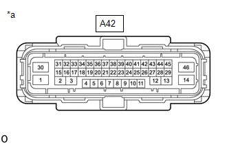
*a |
Component without harness connected (Skid Control ECU (Brake Actuator Assembly)) |
- |
- |
|
Terminal No. (Symbol) |
Terminal Description |
|---|---|
|
1 (+BM) |
ABS motor relay power supply |
|
2 |
- |
|
3 |
- |
|
4 |
- (Not used) |
|
5 (CANH) |
CAN communication line H |
|
6 (CSW) |
VSC OFF switch input |
|
7 (FL-) |
Front wheel speed LH (-) signal input |
|
8 |
- (Not used) |
|
9 |
- (Not used) |
|
10 (STPO) |
Stop light control relay output |
|
11 |
- (Not used) |
|
12 |
- |
|
13 |
- |
|
14 (GND2) |
Pump motor ground |
|
15 |
- |
|
16 |
- |
|
17 (FSW+) |
Brake pedal load sensing switch input |
|
18 |
- (Not used) |
|
19 (CANL) |
CAN communication line L |
|
20 |
- (Not used) |
|
21 (FR+) |
Front wheel speed RH (+) signal input |
|
22 (RR+) |
Rear wheel speed RH (+) signal input |
|
23 (RL-) |
Rear wheel speed LH (-) signal input |
|
24 (FL+) |
Front wheel speed LH (+) signal input |
|
25 |
- (Not used) |
|
26 (FR-) |
Front wheel speed RH (-) signal input |
|
27 |
- (Not used) |
|
28 |
- (Not used) |
|
29 |
- (Not used) |
|
30 (+BS) |
ABS solenoid relay power supply |
|
31 |
- |
|
32 |
- |
|
33 |
- |
|
34 (SP1) |
Speed signal output for speedometer |
|
35 |
- |
|
36 (IG1) |
IG1 power source input |
|
37 (RR-) |
Rear wheel speed RH (-) signal input |
|
38 |
- (Not used) |
|
39 (RL+) |
Rear wheel speed LH (+) signal input |
|
40 |
- (Not used) |
|
41 |
- (Not used) |
|
42 (STP) |
Stop light control relay input |
|
43 (HZRI) |
Brake hold switch input |
|
44 (STP2) |
Stop light switch input |
|
45 |
- |
|
46 (GND1) |
Skid control ECU ground |
TERMINAL INSPECTION
(a) Disconnect the connector and measure the voltage and resistance on the wire harness side.
HINT:
The voltage cannot be measured with the connector connected to the skid control ECU (brake actuator assembly) because the connector is watertight.
Standard|
Terminal No. (Symbol) |
Wiring Color |
Terminal Description |
Condition |
Specified Condition |
|---|---|---|---|---|
|
A42-1 (+BM) - Body ground |
L - Body ground |
ABS motor relay power supply |
Always |
11 to 14 V |
|
A42-6 (CSW) - Body ground |
R - Body ground |
VSC OFF switch input |
VSC OFF switch ON → OFF (Pressed → not pressed) |
Below 1 Ω → 10 kΩ or higher |
|
A42-10 (STPO) - Body ground |
R - Body ground |
Stop light control relay (stop light switch assembly) output |
Ignition switch ON |
11 to 14 V |
|
A42-14 (GND2) - Body ground |
W-B - Body ground |
Pump motor ground |
Always |
Below 1 Ω |
|
A42-17 (FSW+) - Body ground |
GR - Body ground |
Brake pedal load sensing switch input |
Brake pedal load sensing switch OFF → ON (Brake pedal depressed → released) |
950 to 1050 Ω → 203 to 223 Ω |
|
A42-30 (+BS) - Body ground |
W - Body ground |
ABS solenoid relay power supply |
Always |
11 to 14 V |
|
A42-36 (IG1) - Body ground |
B - Body ground |
IG1 power source input |
Ignition switch ON |
11 to 14 V |
|
A42-42 (STP) - Body ground |
SB - Body ground |
Stop light control relay (stop light switch assembly) output |
Stop light switch ON → OFF (Brake pedal depressed → released) |
11 to 14 V* → Below 1.5 V |
|
A42-43 (HZRI) - Body ground |
B - Body ground |
Brake hold switch input |
Brake hold switch ON → OFF (Pressed → not pressed) |
Below 1 Ω → 10 kΩ or higher |
|
A42-44 (STP2) - Body ground |
L - Body ground |
Stop light switch input |
Stop light switch assembly ON → OFF (Brake pedal depressed → released) |
11 to 14 V* → Below 1.5 V |
|
A42-46 (GND1) - Body ground |
W-B - Body ground |
Skid control ECU ground |
Always |
Below 1 Ω |
HINT:
*: The standard voltage value varies depending on the +BS terminal voltage value. The standard voltage is 85% of the +BS terminal voltage.
|
*a |
Front view of wire harness connector (to Skid Control ECU (Brake Actuator Assembly)) |
 Diagnosis System
DIAGNOSIS SYSTEM
DESCRIPTION
When troubleshooting a vehicle with a diagnosis system, the only difference from
the usual troubleshooting procedure is connecting the Techstream to the vehicle
and ...
 Dtc Check / Clear
DTC CHECK / CLEAR
DTC CHECK/CLEAR (When Using TECHSTREAM)
(a) Check for DTCs.
(1) Turn the ignition switch off.
(2) Connect the Techstream to the DLC3.
(3) Turn the ignition switch to ON.
(4) Tu ...
Other materials:
Toyota CH-R Service Manual > Air Conditioning System(for Automatic Air Conditioning System With Top-mounted
Air Conditioner Pressure Sensor): PTC Heater Circuit
DESCRIPTION
The air conditioning amplifier assembly sends operation signals to the PTC heater
relays when quick heater assembly operation conditions are met. Based on the signals
from the air conditioning amplifier assembly, the PTC heater relays turn on, and
power is supplied to the quick he ...
Toyota CH-R Service Manual > Maintenance: Front Turn Signal Light Bulb
Components
COMPONENTS
ILLUSTRATION
*1
FRONT TURN SIGNAL LIGHT BULB
*2
FRONT TURN SIGNAL LIGHT SOCKET AND WIRE SUB-ASSEMBLY
Removal
REMOVAL
CAUTION / NOTICE / HINT
HINT:
Use the same procedure for the RH and LH sides.
The ...
Toyota C-HR (AX20) 2023-2026 Owner's Manual
Toyota CH-R Owners Manual
- For safety and security
- Instrument cluster
- Operation of each component
- Driving
- Interior features
- Maintenance and care
- When trouble arises
- Vehicle specifications
- For owners
Toyota CH-R Service Manual
- Introduction
- Maintenance
- Audio / Video
- Cellular Communication
- Navigation / Multi Info Display
- Park Assist / Monitoring
- Brake (front)
- Brake (rear)
- Brake Control / Dynamic Control Systems
- Brake System (other)
- Parking Brake
- Axle And Differential
- Drive Shaft / Propeller Shaft
- K114 Cvt
- 3zr-fae Battery / Charging
- Networking
- Power Distribution
- Power Assist Systems
- Steering Column
- Steering Gear / Linkage
- Alignment / Handling Diagnosis
- Front Suspension
- Rear Suspension
- Tire / Wheel
- Tire Pressure Monitoring
- Door / Hatch
- Exterior Panels / Trim
- Horn
- Lighting (ext)
- Mirror (ext)
- Window / Glass
- Wiper / Washer
- Door Lock
- Heating / Air Conditioning
- Interior Panels / Trim
- Lighting (int)
- Meter / Gauge / Display
- Mirror (int)
- Power Outlets (int)
- Pre-collision
- Seat
- Seat Belt
- Supplemental Restraint Systems
- Theft Deterrent / Keyless Entry

0.0076