Toyota CH-R Service Manual: Dtc Check / Clear
DTC CHECK / CLEAR
DTC CHECK/CLEAR (When Using TECHSTREAM)
(a) Check for DTCs.
(1) Turn the ignition switch off.
(2) Connect the Techstream to the DLC3.
(3) Turn the ignition switch to ON.
(4) Turn the Techstream on.
(5) Read the DTCs following the prompts on the Techstream. Enter the following menus: Chassis / ABS/VSC/TRAC/EPB / Trouble Codes.
Chassis > ABS/VSC/TRAC/EPB > Trouble Codes(6) Check the details of the DTCs.
Click here
.gif)
NOTICE:
The vehicle stability control system outputs DTCs for the following system. When DTCs other than those in Diagnostic Trouble Code Chart for the vehicle stability control system are output, refer to Diagnostic Trouble Code Chart for the relevant system.
|
System |
Proceed to |
|---|---|
|
Electric Parking Brake System |
|
(b) Clear the DTCs.
(1) Turn the ignition switch off.
(2) Connect the Techstream to the DLC3.
(3) Turn the ignition switch to ON.
(4) Turn the Techstream on.
(5) Operate the Techstream to clear the codes. Enter the following menus: Chassis / ABS/VSC/TRAC/EPB / Trouble Codes.
Chassis > ABS/VSC/TRAC/EPB > Clear DTCs(6) Press the DTC clear button.
DTC CHECK/CLEAR (When Using SST Check Wire)
(a) Check for DTCs.
(1) Turn the ignition switch off.
(2) Using SST, connect terminals TC and CG of the DLC3.
SST: 09843-18040
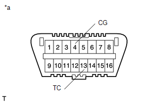
|
*a |
Front view of DLC3 |
(3) Turn the ignition switch to ON.
(4) Observe the blinking pattern of the ABS warning, slip indicator and brake hold standby indicator lights in order to identify the DTC.
HINT:
If no code appears, inspect the TC and CG terminal circuit, and ABS warning, slip indicator and brake hold standby indicator light circuits.
|
Trouble Area |
See Procedure |
|---|---|
|
TC and CG terminal circuit |
|
|
ABS warning light circuit (Remains on) |
|
|
ABS warning light circuit (Does not come on) |
|
|
Slip indicator light circuit (Remains on) |
|
|
Slip indicator light circuit (Does not come on) |
|
|
Brake hold standby indicator light circuit |
|
(5) Count the number of blinks of the ABS warning and slip indicator lights.
HINT:
- When the system is operating correctly, each light will blink continuously in a pattern of 0.25 seconds on, and then 0.25 seconds off.
- When one DTC is output, each light will output the same code at 4 second intervals (for example, code 21 would be output as 2 blinks, a 1.5 second pause, and then 1 blink).
- When 2 or more DTCs are output, each light will output a different code at 2.5 second intervals, and when all codes have been output, there will be a 4 second pause and the sequence will repeat.
- When multiple codes are stored, they are output in order starting with the lowest DTC number.
- If the brake hold operated indicator light is blinking before terminals of the DLC3 are connected, when terminals 13 (TC) and 4 (CG) of the DLC3 are connected, the brake hold operated indicator light stops blinking and turns off.
(6) Check the details of the DTCs.
ABS DTC|
ABS Warning Light Display |
Tester Display |
|---|---|
|
11 |
C146E |
|
13 |
C146C |
|
21 |
C1468 |
|
22 |
C1469 |
|
23 |
C146A |
|
24 |
C146B |
|
25 |
C1225 |
|
26 |
C1226 |
|
27 |
C1227 |
|
28 |
C1228 |
|
31 |
C1464 |
|
32 |
C1465 |
|
33 |
C1466 |
|
34 |
C1467 |
|
35 |
C1330 |
|
36 |
C1331 |
|
37 |
C1237 |
|
38 |
C1332 |
|
39 |
C1333 |
|
41 |
C1241 |
|
C1417 |
|
|
43 |
C1243 |
|
44 |
C1419 |
|
C1420 |
|
|
C1474 |
|
|
45 |
C1245 |
|
46 |
C1246 |
|
49 |
C1249 |
|
C1425 |
|
|
C1426 |
|
|
51 |
C1428 |
|
62 |
C1300 |
|
67 |
C1429 |
|
C1430 |
|
|
C1431 |
|
|
94 |
U0073 |
|
97 |
C1381 |
|
Slip Indicator Light Display |
Tester Display |
|---|---|
|
28 |
C1472 |
|
C1474 |
|
|
31 |
C1432 |
|
C1433 |
|
|
C1434 |
|
|
C1439 |
|
|
C1445 |
|
|
32 |
C1419 |
|
C1420 |
|
|
34 |
C1234 |
|
C1435 |
|
|
C1436 |
|
|
39 |
C1336 |
|
43*1 |
- |
|
44 |
C1224 |
|
51 |
C1201 |
|
62 |
U0123 |
|
63 |
U0126 |
|
64 |
C1380 |
|
65 |
U0100 |
|
6A*2 |
C1381 |
|
88 |
C1288 |
|
98 |
C1448 |
|
- |
C1441 |
|
Warning Light Display |
Tester Display |
|---|---|
|
11*3 |
- |
|
14*4 |
- |
|
58 |
U0142 |
- *1: This DTC is output when the VSC system detects a malfunction in the ABS.
- *2: The light blinks 6 times, turns off for 1.5 seconds, and then blinks 10 times.
- *3: This DTC is output when the Brake Hold system detects a malfunction in the VSC.
- *4: This DTC is output when the Brake Hold system detects a malfunction in the EPB.
(7) After completing the check, disconnect terminals TC and CG of the DLC3 to turn off the display.
If 2 or more DTCs are detected at the same time, the DTCs will be displayed in ascending order.
(b) Clear the DTCs.
(1) Turn the ignition switch off.
(2) Using SST, connect terminals TC and CG of the DLC3.
SST: 09843-18040
|
*a |
Front view of DLC3 |
(3) Turn the ignition switch to ON.
(4) Clear the DTCs stored in the ECU by depressing the brake pedal 8 times or more within 5 seconds.
(5) Check that the ABS warning and slip indicator lights indicate the normal system code.
(6) Remove SST from the terminals of the DLC3.
HINT:
The DTCs cannot be cleared by disconnecting the battery terminal or the ECU-IG NO. 1 fuse.
END OF DTC CHECK/CLEAR
(a) Turn the ignition switch to ON.
(b) Check that the ABS warning and slip indicator lights go off within approximately 3 seconds of turning the ignition switch to ON.
 Terminals Of Ecu
TERMINALS OF ECU
TERMINALS OF ECU
*a
Component without harness connected
(Skid Control ECU (Brake Actuator Assembly))
-
-
Termin ...
 Freeze Frame Data
FREEZE FRAME DATA
FREEZE FRAME DATA
(a) Whenever an ABS DTC is detected, the skid control ECU (brake actuator assembly)
stores the current vehicle (ECU or sensor) state as Freeze Frame Data.
(b) ...
Other materials:
Toyota CH-R Owners Manual > Engine compartment: Brake fluid
■ Checking fluid level
The brake fluid level should be between the "MAX" and "MIN" lines on the tank.
■ Adding fluid
1. Slide and lift up the rubber strip to partly remove it as shown.
2. Disconnect the claws and remove the service cover.
3. Remove the reserv ...
Toyota CH-R Service Manual > Front Seat Outer Belt Assembly: Disposal
DISPOSAL
CAUTION / NOTICE / HINT
CAUTION:
Before performing pre-disposal deployment of any SRS part, review and closely
follow all applicable environmental and hazardous material regulations. Pre-disposal
deployment may be considered hazardous material treatment.
PROCEDURE
1. PRECAUTION
...
Toyota C-HR (AX20) 2023-2026 Owner's Manual
Toyota CH-R Owners Manual
- For safety and security
- Instrument cluster
- Operation of each component
- Driving
- Interior features
- Maintenance and care
- When trouble arises
- Vehicle specifications
- For owners
Toyota CH-R Service Manual
- Introduction
- Maintenance
- Audio / Video
- Cellular Communication
- Navigation / Multi Info Display
- Park Assist / Monitoring
- Brake (front)
- Brake (rear)
- Brake Control / Dynamic Control Systems
- Brake System (other)
- Parking Brake
- Axle And Differential
- Drive Shaft / Propeller Shaft
- K114 Cvt
- 3zr-fae Battery / Charging
- Networking
- Power Distribution
- Power Assist Systems
- Steering Column
- Steering Gear / Linkage
- Alignment / Handling Diagnosis
- Front Suspension
- Rear Suspension
- Tire / Wheel
- Tire Pressure Monitoring
- Door / Hatch
- Exterior Panels / Trim
- Horn
- Lighting (ext)
- Mirror (ext)
- Window / Glass
- Wiper / Washer
- Door Lock
- Heating / Air Conditioning
- Interior Panels / Trim
- Lighting (int)
- Meter / Gauge / Display
- Mirror (int)
- Power Outlets (int)
- Pre-collision
- Seat
- Seat Belt
- Supplemental Restraint Systems
- Theft Deterrent / Keyless Entry

0.0129