Toyota CH-R Service Manual: Terminals Of Ecu
TERMINALS OF ECU
CHECK INSTRUMENT PANEL JUNCTION BLOCK ASSEMBLY AND MAIN BODY ECU (MULTIPLEX NETWORK BODY ECU)
|
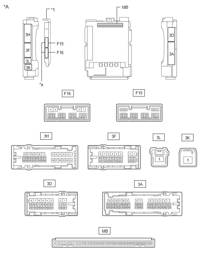
*A |
Main Body ECU (Multiplex Network Body ECU) with 2 Connectors |
- |
- |
|
*1 |
Main Body ECU (Multiplex Network Body ECU) |
- |
- |
|
*a |
2 Connectors |
- |
- |
|
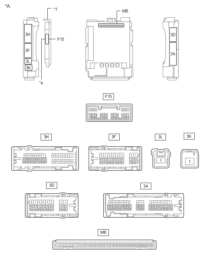
*A |
Main Body ECU (Multiplex Network Body ECU) with 1 Connector |
- |
- |
|
*1 |
Main Body ECU (Multiplex Network Body ECU) |
- |
- |
|
*a |
1 Connector |
- |
- |
(a) Disconnect the instrument panel junction block assembly and main body ECU (multiplex network body ECU) connectors.
(b) Measure the voltage on the wire harness side connector according to the value(s) in the table below.
|
Terminal No. (Symbol) |
Wiring Color |
Terminal Description |
Condition |
Specified Condition |
|---|---|---|---|---|
|
3F-1 - Body ground |
W - Body ground |
Battery power supply |
Always |
11 to 14 V |
|
3K-1 - Body ground |
B-R - Body ground |
Battery power supply |
Always |
11 to 14 V |
If the result is not as specified, there may be a malfunction in the wire harness.
(c) Measure the resistance on the wire harness side connector according to the value(s) in the table below.
|
Terminal No. (Symbol) |
Wiring Color |
Terminal Description |
Condition |
Specified Condition |
|---|---|---|---|---|
|
3D-3 - Body ground |
W-B - Body ground |
Ground |
Always |
Below 1 Ω |
If the result is not as specified, there may be a malfunction in the wire harness.
(d) Reconnect the instrument panel junction block assembly and main body ECU (multiplex network body ECU) connectors.
(e) Measure the voltage and check for pulses according to the value(s) in the table below.
|
Terminal No. (Symbol) |
Wiring Color |
Terminal Description |
Condition |
Specified Condition |
|---|---|---|---|---|
|
3F-31 - Body ground |
G - Body ground |
H-LP LH relay drive output |
Ignition switch off |
11 to 14 V |
|
Ignition switch ON |
Below 1 V |
|||
|
F15-1 (DIM) - Body ground |
Y - Body ground |
H-LP RH relay drive output |
Ignition switch off |
11 to 14 V |
|
Ignition switch ON |
Below 1 V |
|||
|
F15-8 (A) - Body ground |
W - Body ground |
Light control switch AUTO position signal input |
Light control switch in AUTO position |
Below 1 V |
|
Light control switch not in AUTO position |
Pulse generation |
|||
|
F15-12 (HEAD) - Body ground |
L - Body ground |
Light control switch head position input |
Light control switch in head position |
Below 1 V |
|
Light control switch not in head position |
Pulse generation |
|||
|
F15-17 (AHBI) - Body ground |
Y - Body ground |
Auto high beam switch signal input |
Ignition switch on, auto high beam switch off |
11 to 14 V |
|
Ignition switch on, auto high beam switch on |
Below 1 V |
|||
|
F15-19 (CLTB) - F15-21 (CLTE) |
G - V |
Automatic light control sensor power supply output |
Ignition switch off |
Below 1 V |
|
Ignition switch ON |
11 to 14 V |
|||
|
F15-20 (CLTS) -Body ground |
BE - Body ground |
Automatic lightcontrol sensor signalinput |
Ignition switch off |
Below 1 V |
|
Automatic lightcontrol systemoperating |
Communicationwaveformgeneration(See waveform 1) |
|||
|
F15-20 (CLTS) - Body ground |
BE - Body ground |
Automatic light control sensor signal input |
Ignition switch off |
Below 1 V |
|
Automatic light control system operating |
Communication waveform generation (See waveform 1) |
|||
|
F15-24 (HU) - Body ground |
GR - Body ground |
Dimmer switch high position signal input |
Dimmer switch in high position |
Below 1 V |
|
Dimmer switch not in high position |
Pulse generation |
- *1: If the light switch has no OFF position, set the light switch to "Auto" with the Lo beam turned off. If the Lo beam is illuminated, shine a fluorescent light or other light source onto the light sensor to enter daytime mode.
If the result is not as specified, the main body ECU (multiplex network body ECU) or instrument panel junction block assembly may be malfunctioning.
(1) Waveform 1
|
Item |
Content |
|---|---|
|
Tool setting |
2 V/DIV., 10 ms./DIV. |
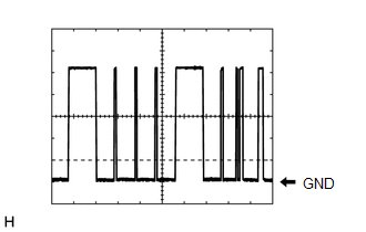
HINT:
The communication waveform changes according to the surrounding brightness.
CHECK HEADLIGHT ECU SUB-ASSEMBLY LH (for LED Headlight)
Click here
.gif)
CHECK HEADLIGHT ECU SUB-ASSEMBLY RH (for LED Headlight)
Click here
CHECK FORWARD RECOGNITION CAMERA
Click here
 Problem Symptoms Table
PROBLEM SYMPTOMS TABLE
NOTICE:
Before replacing the main body ECU (multiplex network body ECU), refer
to registration.*1
*1: w/ Smart Key System
When replacing the forward reco ...
 Diagnosis System
DIAGNOSIS SYSTEM
DESCRIPTION
(a) Automatic high beam system data and Diagnostic Trouble Codes (DTCs) can be
read from the Data Link Connector 3 (DLC3) of the vehicle. When the system seems
to be ...
Other materials:
Toyota CH-R Owners Manual > For safe use: Front passenger occupant classification system
Your vehicle is equipped with a front passenger occupant classification
system. This system detects the conditions of the front passenger seat and activates
or deactivates the devices for the front passenger.
SRS warning light
Seat belt reminder light
"AIR BAG O ...
Toyota CH-R Owners Manual > Maintenance: General maintenance
Listed below are the general maintenance items that should be performed
at the intervals specified in the "Owner's Warranty Information Booklet" or "Owner's
Manual Supplement/Scheduled Maintenance Guide". It is recommended that any problem
you notice should be broug ...
Toyota C-HR (AX20) 2023-2026 Owner's Manual
Toyota CH-R Owners Manual
- For safety and security
- Instrument cluster
- Operation of each component
- Driving
- Interior features
- Maintenance and care
- When trouble arises
- Vehicle specifications
- For owners
Toyota CH-R Service Manual
- Introduction
- Maintenance
- Audio / Video
- Cellular Communication
- Navigation / Multi Info Display
- Park Assist / Monitoring
- Brake (front)
- Brake (rear)
- Brake Control / Dynamic Control Systems
- Brake System (other)
- Parking Brake
- Axle And Differential
- Drive Shaft / Propeller Shaft
- K114 Cvt
- 3zr-fae Battery / Charging
- Networking
- Power Distribution
- Power Assist Systems
- Steering Column
- Steering Gear / Linkage
- Alignment / Handling Diagnosis
- Front Suspension
- Rear Suspension
- Tire / Wheel
- Tire Pressure Monitoring
- Door / Hatch
- Exterior Panels / Trim
- Horn
- Lighting (ext)
- Mirror (ext)
- Window / Glass
- Wiper / Washer
- Door Lock
- Heating / Air Conditioning
- Interior Panels / Trim
- Lighting (int)
- Meter / Gauge / Display
- Mirror (int)
- Power Outlets (int)
- Pre-collision
- Seat
- Seat Belt
- Supplemental Restraint Systems
- Theft Deterrent / Keyless Entry

0.0074