Toyota CH-R Service Manual: Components
COMPONENTS
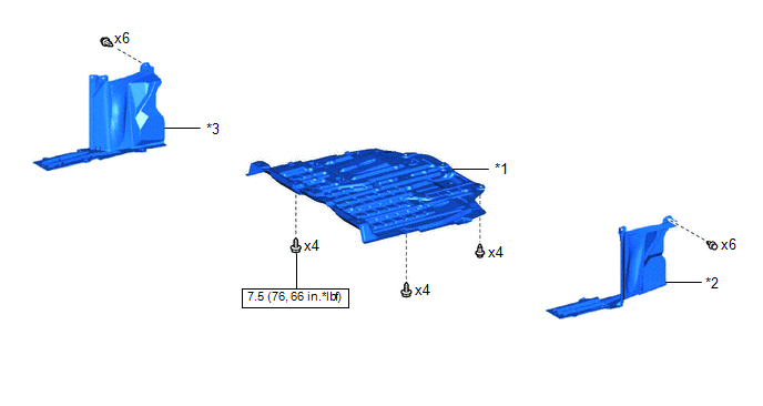
ILLUSTRATION
|
*1 |
NO. 1 ENGINE UNDER COVER |
*2 |
REAR ENGINE UNDER COVER LH |
|
*3 |
REAR ENGINE UNDER COVER RH |
- |
- |
.png) |
N*m (kgf*cm, ft.*lbf): Specified torque |
- |
- |
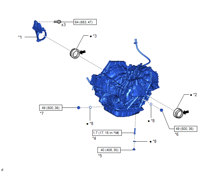
ILLUSTRATION
|
*1 |
DRIVE SHAFT BEARING BRACKET |
*2 |
FRONT DRIVE SHAFT OIL SEAL LH |
|
*3 |
FRONT DRIVE SHAFT OIL SEAL RH |
*4 |
NO. 1 TRANSMISSION OIL FILLER TUBE |
|
*5 |
OVERFLOW PLUG |
*6 |
REFILL PLUG |
|
*7 |
DRAIN PLUG |
*8 |
GASKET |
|
|
N*m (kgf*cm, ft.*lbf): Specified torque |
● |
Non-reusable part |
.png) |
MP grease |
- |
- |

 Replacement
REPLACEMENT
CAUTION / NOTICE / HINT
The necessary procedures (adjustment, calibration, initialization, or registration)
that must be performed after parts are removed, installed, or replaced durin ...
Other materials:
Toyota CH-R Service Manual > Airbag System: Short in Curtain Shield Squib LH Circuit (B1835/58-B1838/58)
DESCRIPTION
The curtain shield squib LH circuit consists of the airbag sensor assembly and
curtain shield airbag assembly LH.
The airbag sensor assembly uses this circuit to deploy the airbag when deployment
conditions are met.
These DTCs are stored when a malfunction is detected in the curta ...
Toyota CH-R Service Manual > Vehicle Stability Control System: Check For Intermittent Problems
CHECK FOR INTERMITTENT PROBLEMS
CHECK FOR INTERMITTENT PROBLEMS
HINT:
A momentary interruption (open circuit) in the connectors and/or wire harness
between the sensors and ECUs can be detected using the Data List function of the
Techstream.
(a) Turn the ignition switch off.
(b) Connect the ...
Toyota C-HR (AX20) 2023-2026 Owner's Manual
Toyota CH-R Owners Manual
- For safety and security
- Instrument cluster
- Operation of each component
- Driving
- Interior features
- Maintenance and care
- When trouble arises
- Vehicle specifications
- For owners
Toyota CH-R Service Manual
- Introduction
- Maintenance
- Audio / Video
- Cellular Communication
- Navigation / Multi Info Display
- Park Assist / Monitoring
- Brake (front)
- Brake (rear)
- Brake Control / Dynamic Control Systems
- Brake System (other)
- Parking Brake
- Axle And Differential
- Drive Shaft / Propeller Shaft
- K114 Cvt
- 3zr-fae Battery / Charging
- Networking
- Power Distribution
- Power Assist Systems
- Steering Column
- Steering Gear / Linkage
- Alignment / Handling Diagnosis
- Front Suspension
- Rear Suspension
- Tire / Wheel
- Tire Pressure Monitoring
- Door / Hatch
- Exterior Panels / Trim
- Horn
- Lighting (ext)
- Mirror (ext)
- Window / Glass
- Wiper / Washer
- Door Lock
- Heating / Air Conditioning
- Interior Panels / Trim
- Lighting (int)
- Meter / Gauge / Display
- Mirror (int)
- Power Outlets (int)
- Pre-collision
- Seat
- Seat Belt
- Supplemental Restraint Systems
- Theft Deterrent / Keyless Entry

0.0098