Toyota CH-R Service Manual: Input / Turbine Speed Sensor "B" Circuit No Signal (P2767)
DESCRIPTION
The ECM detects the input shaft speed based on the signal from the transmission revolution sensor (NIN) and performs gear ratio control.
|
DTC No. |
Detection Item |
DTC Detection Condition |
Trouble Area |
MIL |
Memory |
|---|---|---|---|---|---|
|
P2767 |
Input / Turbine Speed Sensor "B" Circuit No Signal |
While the vehicle is driven with the shift lever in D, and the output shaft speed is 300 rpm or more (vehicle speed is approximately 6 km/h (4 mph) or more), the speed indicated by the transmission revolution sensor (NIN) is less than 300 rpm for 2 seconds (1 trip detection logic). |
|
Comes on |
DTC stored |
MONITOR DESCRIPTION
The ECM receives a signal from the transmission revolution sensor (NIN) installed to the continuously variable transaxle and determines the input shaft speed in order to control the gear ratio. If the ECM detects no signal from the transmission revolution sensor (NIN) even while the vehicle is moving, it will determine that there is a malfunction in the transmission revolution sensor (NIN), illuminate the MIL and store this DTC.
MONITOR STRATEGY
|
Related DTCs |
P2767: Primary pulley speed sensor (NIN) / Verify pulse input |
|
Required sensors/Components |
Transmission revolution sensor (NIN) |
|
Frequency of operation |
Continuous |
|
Duration Conditions |
2 seconds |
|
MIL operation |
Immediately |
|
Sequence of operation |
None |
TYPICAL ENABLING CONDITIONS
All of the following conditions are met :|
Battery voltage |
8 V or more |
|
Time after Battery voltage 8 V or more |
0.5 seconds or more |
|
Write Inhibit |
permit |
|
Time after Write status forbiddance to permit |
0.5 seconds or more |
|
Ignition switch |
ON |
|
Time after Ignition switch OFF to ON |
0.5 seconds or more |
|
Starter |
OFF |
|
Time after Starter ON to OFF |
0.5 seconds or more |
|
Output shaft revolution |
300 rpm or more |
TYPICAL MALFUNCTION THRESHOLDS
|
Input Speed Sensor revolution |
Less than 300 rpm |
COMPONENT OPERATING RANGE
|
Input Speed Sensor revolution |
300 rpm or more |
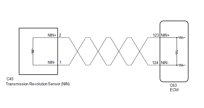
WIRING DIAGRAM
CAUTION / NOTICE / HINT
NOTICE:
- Perform initialization after replacing any parts related to the continuously
variable transaxle system.
Click here
.gif)
- Check that no DTCs are stored after performing initialization.
Click here
- Perform the universal trip to clear permanent DTCs.
Click here
HINT:
After performing repair, clear the DTCs and perform the following procedure to check that DTCs are not output.
- Drive the vehicle for 2 seconds or more at 6 km/h (4 mph) or more with the shift lever in D.
- Check for DTCs again.
Click here
PROCEDURE
|
1. |
READ VALUE USING TECHSTREAM (SPD (NIN), ENGINE SPEED AND LOCK UP) |
(a) Connect the Techstream to the DLC3.
(b) Turn the ignition switch to ON.
(c) Turn the Techstream on.
(d) Enter the following menus: Powertrain / Engine and ECT / Data List.
Powertrain > Engine and ECT > Data List|
Tester Display |
|---|
|
Engine Speed |
|
SPD (NIN) |
|
Lock Up |
(e) In accordance with the display on the Techstream, read the Data List.
Powertrain > Engine and ECT > Data List|
Tester Display |
Measurement Item |
Range |
Normal Condition |
Diagnostic Note |
|---|---|---|---|---|
|
Engine Speed |
Engine speed |
Min.: 0 rpm Max.: 16383 rpm |
710 to 810 rpm: Idling |
When the crankshaft position sensor is malfunctioning, "Engine Speed" is approximately 0 rpm or varies greatly from the actual engine speed. |
|
SPD (NIN) |
Primary pulley speed (NIN) |
Min.: 0 rpm Max.: 12750 rpm |
|
Data is displayed in increments of 50 rpm. |
|
Lock Up |
Lock-up |
OFF or ON |
|
- |
|
Result |
Proceed to |
|---|---|
|
Data display is not within Normal Condition range |
A |
|
Data display is within Normal Condition range |
B |
| B | .gif) |
GO TO STEP 5 |
|
.gif)
|
2. |
INSPECT TRANSMISSION REVOLUTION SENSOR (NIN) |
|
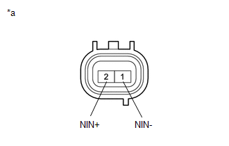
(a) Disconnect the C45 transmission revolution sensor (NIN) connector. |
|
(b) Measure the resistance according to the value(s) in the table below.
Standard Resistance:
|
Tester Connection |
Condition |
Specified Condition |
|---|---|---|
|
1 (NIN-) - 2 (NIN+) |
20°C (68°F) |
560 to 680 Ω |
| NG | |
REPLACE TRANSMISSION REVOLUTION SENSOR (NIN) |
|
|
3. |
CHECK HARNESS AND CONNECTOR (TRANSMISSION REVOLUTION SENSOR (NIN) - ECM) |
|
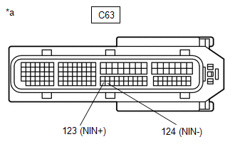
(a) Disconnect the ECM connector. |
|
(b) Measure the resistance according to the value(s) in the table below.
Standard Resistance:
|
Tester Connection |
Condition |
Specified Condition |
|---|---|---|
|
C63-123 (NIN+) - C63-124 (NIN-) |
20°C (68°F) |
560 to 680 Ω |
|
C63-123 (NIN+) - Body ground and other terminals |
Always |
10 kΩ or higher |
|
C63-124 (NIN-) - Body ground and other terminals |
Always |
10 kΩ or higher |
| NG | |
REPAIR OR REPLACE HARNESS OR CONNECTOR (TRANSMISSION REVOLUTION SENSOR (NIN) - ECM) |
|
|
4. |
REPLACE ECM |
(a) Replace the ECM.
Click here
| NEXT | |
PERFORM INITIALIZATION
|
|
5. |
REPLACE ECM |
(a) Replace the ECM.
Click here
| NEXT | |
PERFORM INITIALIZATION
|
 Pressure Control Solenoid "J" Performance or Stuck Off (P2820)
DESCRIPTION
According to current control by the ECM, the shift solenoid valve SLP controls
primary pulley pressure in accordance with the requested gear ratio to perform gear
ratio changes.
...
 Acceleration Sensor Learning Value (P1589)
DESCRIPTION
The ECM stores DTC P1589 if deceleration sensor zero point calibration is not
performed or failed after system components such as the ECM are replaced.
DTC No.
De ...
Other materials:
Toyota CH-R Service Manual > Rear Axle Hub: Components
COMPONENTS
ILLUSTRATION
*1
REAR AXLE HUB AND BEARING ASSEMBLY
*2
REAR DISC
*3
REAR DISC BRAKE CALIPER ASSEMBLY
*4
REAR FLEXIBLE HOSE
*5
REAR DISC BRAKE DUST COVER SUB-ASSEMBL ...
Toyota CH-R Service Manual > Vehicle Stability Control System: Speed Sensor Rotor Faulty (C1237)
DESCRIPTION
The skid control ECU (brake actuator assembly) measures the speed of each wheel
by receiving signals from each speed sensor.
These signals are used for recognizing that all four wheels are operating properly.
Therefore, signals from all wheels must be equal.
DTC No.
...
Toyota C-HR (AX20) 2023-2026 Owner's Manual
Toyota CH-R Owners Manual
- For safety and security
- Instrument cluster
- Operation of each component
- Driving
- Interior features
- Maintenance and care
- When trouble arises
- Vehicle specifications
- For owners
Toyota CH-R Service Manual
- Introduction
- Maintenance
- Audio / Video
- Cellular Communication
- Navigation / Multi Info Display
- Park Assist / Monitoring
- Brake (front)
- Brake (rear)
- Brake Control / Dynamic Control Systems
- Brake System (other)
- Parking Brake
- Axle And Differential
- Drive Shaft / Propeller Shaft
- K114 Cvt
- 3zr-fae Battery / Charging
- Networking
- Power Distribution
- Power Assist Systems
- Steering Column
- Steering Gear / Linkage
- Alignment / Handling Diagnosis
- Front Suspension
- Rear Suspension
- Tire / Wheel
- Tire Pressure Monitoring
- Door / Hatch
- Exterior Panels / Trim
- Horn
- Lighting (ext)
- Mirror (ext)
- Window / Glass
- Wiper / Washer
- Door Lock
- Heating / Air Conditioning
- Interior Panels / Trim
- Lighting (int)
- Meter / Gauge / Display
- Mirror (int)
- Power Outlets (int)
- Pre-collision
- Seat
- Seat Belt
- Supplemental Restraint Systems
- Theft Deterrent / Keyless Entry

0.0105