Toyota CH-R Service Manual: Parts Location
PARTS LOCATION
ILLUSTRATION
|
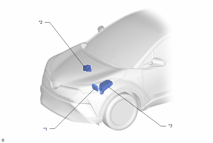
*1 |
ECM |
*2 |
SKID CONTROL ECU (BRAKE ACTUATOR ASSEMBLY) |
|
*3 |
NO. 1 ENGINE ROOM RELAY BLOCK - EFI-MAIN NO. 1 RELAY - EFI-MAIN NO. 1 FUSE - EFI NO. 2 FUSE - ECU-IG2 NO. 1 FUSE - ECU-B NO. 3 FUSE - IG2-MAIN FUSE - ETCS FUSE |
- |
- |
ILLUSTRATION
|
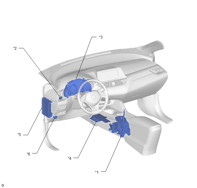
*1 |
SHIFT LOCK CONTROL UNIT ASSEMBLY - TRANSMISSION CONTROL SWITCH |
*2 |
STOP LIGHT SWITCH ASSEMBLY |
|
*3 |
COMBINATION METER ASSEMBLY |
*4 |
AIRBAG SENSOR ASSEMBLY - YAW RATE AND ACCELERATION SENSOR |
|
*5 |
INSTRUMENT PANEL JUNCTION BLOCK ASSEMBLY - IG2 NO. 1 RELAY - ECU-IG1 NO. 1 FUSE - BKUP LP FUSE - AM2 FUSE |
*6 |
DLC3 |
ILLUSTRATION
|
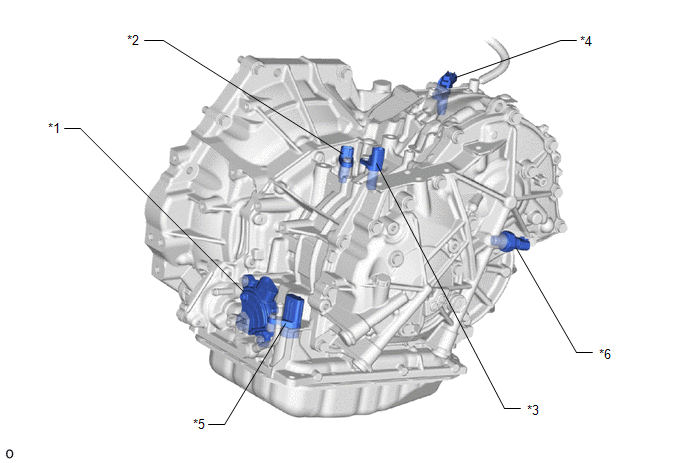
*1 |
PARK/NEUTRAL POSITION SWITCH |
*2 |
TRANSMISSION REVOLUTION SENSOR (NT) |
|
*3 |
TRANSMISSION REVOLUTION SENSOR (NIN) |
*4 |
TRANSMISSION REVOLUTION SENSOR (NOUT) |
|
*5 |
TRANSMISSION WIRE |
*6 |
OIL PRESSURE SENSOR |
 Precaution
PRECAUTION
IGNITION SWITCH EXPRESSION
HINT:
The type of ignition switch used on this model differs depending on the specifications
of the vehicle. The expressions listed in the table below are us ...
 System Diagram
SYSTEM DIAGRAM
...
Other materials:
Toyota CH-R Service Manual > Rear Disc Brake Pad(for Tmc Made): Components
COMPONENTS
ILLUSTRATION
*1
REAR DISC BRAKE CYLINDER ASSEMBLY
*2
REAR NO. 2 DISC BRAKE ANTI-SQUEAL SHIM
*3
REAR NO. 1 DISC BRAKE ANTI-SQUEAL SHIM
*4
REAR DISC BRAKE ANTI-SQUEAL SHIM KIT
...
Toyota CH-R Service Manual > Fog Light Assembly: Adjustment
ADJUSTMENT
PROCEDURE
1. PREPARE VEHICLE FOR FOG LIGHT AIM ADJUSTMENT
(a) Prepare the vehicle:
Ensure that there is no damage or deformation to the vehicle body around
the fog lights.
Fill the fuel tank.
Make sure that the oil is filled to the specified level.
Make sure tha ...
Toyota C-HR (AX20) 2023-2026 Owner's Manual
Toyota CH-R Owners Manual
- For safety and security
- Instrument cluster
- Operation of each component
- Driving
- Interior features
- Maintenance and care
- When trouble arises
- Vehicle specifications
- For owners
Toyota CH-R Service Manual
- Introduction
- Maintenance
- Audio / Video
- Cellular Communication
- Navigation / Multi Info Display
- Park Assist / Monitoring
- Brake (front)
- Brake (rear)
- Brake Control / Dynamic Control Systems
- Brake System (other)
- Parking Brake
- Axle And Differential
- Drive Shaft / Propeller Shaft
- K114 Cvt
- 3zr-fae Battery / Charging
- Networking
- Power Distribution
- Power Assist Systems
- Steering Column
- Steering Gear / Linkage
- Alignment / Handling Diagnosis
- Front Suspension
- Rear Suspension
- Tire / Wheel
- Tire Pressure Monitoring
- Door / Hatch
- Exterior Panels / Trim
- Horn
- Lighting (ext)
- Mirror (ext)
- Window / Glass
- Wiper / Washer
- Door Lock
- Heating / Air Conditioning
- Interior Panels / Trim
- Lighting (int)
- Meter / Gauge / Display
- Mirror (int)
- Power Outlets (int)
- Pre-collision
- Seat
- Seat Belt
- Supplemental Restraint Systems
- Theft Deterrent / Keyless Entry

0.0101