Toyota CH-R Service Manual: Adjustment
ADJUSTMENT
PROCEDURE
1. PRECAUTIONS AND WORK DESCRIPTION
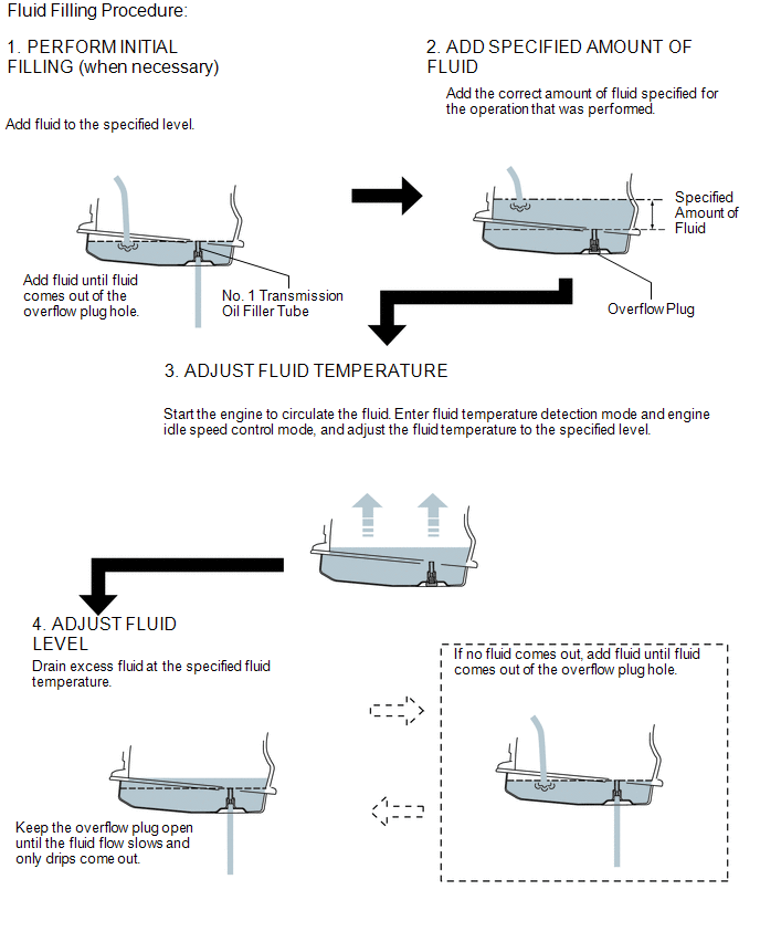
(a) The K114 continuously variable transaxle assembly does not have an oil filler tube or oil level gauge. When adding fluid, add fluid through the refill hole in the continuously variable transaxle assembly. The fluid level can be adjusted by draining excess fluid (allowing excess fluid to overflow) through the No. 1 transmission oil filler tube of the transaxle oil (CVT) pan sub-assembly.
HINT:
"Overflow" indicates the condition under which fluid comes out of the overflow plug hole.
(b) When adding fluid, add the specified amount of fluid while the engine assembly is cold. Then, warm up the engine assembly to circulate the fluid in the continuously variable transaxle assembly and adjust the fluid level with the engine idling at the specified fluid temperature.
(c) The K114 continuously variable transaxle assembly requires Toyota Genuine CVT fluid FE.
(d) When adjusting the fluid level, park the vehicle on level ground (make sure that the tilt angle from the front to rear of the vehicle is within +/-1°).
(e) When adjusting the fluid level, turn off all electrical systems, such as the air conditioning, lighting system, electric fan and audio system, to reduce load.
(f) The fluid temperature in the text indicates "A/T Oil Temperature 1" displayed on the Techstream.
(g) Fluid level adjustment should be performed according to the following procedure and notes.
2. WORK FLOW
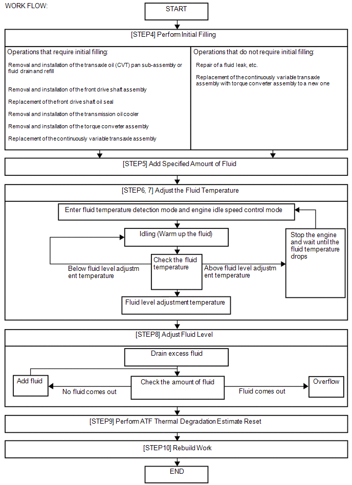
(a) The adjustment should be performed according to the procedures referenced in the work flow below.
3. BEFORE FILLING TRANSAXLE WITH FLUID
NOTICE:
If the continuously variable transaxle assembly is hot (fluid temperature is high), wait until the fluid temperature becomes the same as the ambient temperature before starting the following procedure (recommended fluid temperature: approximately 20°C (68°F)).
(a) Lift the vehicle.
NOTICE:
Set the vehicle on a lift so that the vehicle is kept level when it is lifted up (make sure that the tilt angle from the front to rear of the vehicle is within +/-1°).
(b) Remove the No. 1 engine under cover.
Click here
.gif)
(c) Remove the rear engine under cover LH.
Click here
4. PERFORM INITIAL FILLING
NOTICE:
After performing either of the following operations, it is not necessary to perform the initial filling procedure. Proceed to Add Specified Amount of Fluid (Step 5).
|
Operations that do not Require Initial Filling |
|---|
|
|
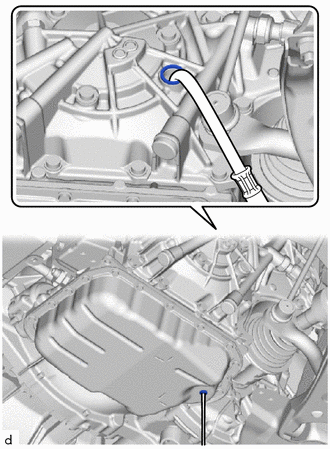
(a) Remove the refill plug and gasket from the continuously variable transaxle assembly. |
|
.png)
|
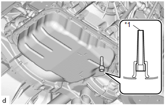
(b) Using a 6 mm hexagon socket wrench, remove the overflow plug and gasket from the transaxle oil (CVT) pan sub-assembly. NOTICE:
|
|
.png)
|
(c) Using a 6 mm hexagon socket wrench, check that the No. 1 transmission oil filler tube is tightened to the specified torque. Torque: 1.7 N·m {17 kgf·cm, 15 in·lbf} NOTICE: If the No. 1 transmission oil filler tube is not tightened to the specified torque, the amount of fluid cannot be precisely adjusted. HINT: To check the torque of the No. 1 transmission oil filler tube, insert a 6 mm hexagon socket wrench into the overflow plug hole. |
|
(d) Perform initial filling.
|
(1) Add fluid to the refill hole until it flows out of the overflow plug hole. NOTICE: Use Toyota Genuine CVT fluid FE. |
|
|
(e) Wait until the fluid flow slows and only drips come out. |
|
.png)
|
(f) Using a 6 mm hexagon socket wrench, temporarily install the gasket and overflow plug to the transaxle oil (CVT) pan sub-assembly. HINT: Reuse the old gasket as the overflow plug will be removed again to adjust the fluid level. |
|
|
(g) Temporarily install the gasket and refill plug to the continuously variable transaxle assembly. HINT: Reuse the old gasket as the refill plug will be removed again to adjust the fluid level. |
|
5. ADD SPECIFIED AMOUNT OF FLUID
|
(a) Remove the refill plug and gasket from the continuously variable transaxle assembly. |
|
|
(b) Fill fluid into the refill hole with the correct amount of fluid as listed in the table below. NOTICE: Use Toyota Genuine CVT fluid FE. HINT: The refill amount differs depending on the operation that was performed. Standard Capacity:
|
|
.png)
|
(c) Temporarily install the gasket and refill plug to the continuously variable transaxle assembly to avoid fluid spillage. HINT: Reuse the old gasket as the refill plug will be removed again to adjust the fluid level. |
|
(d) Lower the vehicle.
6. ADJUST FLUID TEMPERATURE (when Using the Techstream)
(a) Connect the Techstream to the DLC3 with the ignition switch off.
(b) Turn the ignition switch to ON and turn the Techstream on.
NOTICE:
To reduce load, make sure that all electrical systems, such as the air conditioning, lighting system, electric fans and audio system, are off.
(c) Enter the following menus: Powertrain / Engine and ECT / Active Test / Connect the TC and TE1.
Powertrain > Engine and ECT > Active Test|
Active Test Display |
|---|
|
Connect the TC and TE1 |
|
Data List Display |
|---|
|
A/T Oil Temperature 1 |
(d) According to the display on the Techstream, perform the Active Test "Connect the TC and TE1 / ON".
HINT:
The indicator lights on the combination meter blink to indicate that a DTC has been stored when the Active Test "Connect the TC and TE1 / ON" is performed.
(e) Select the Data List item: A/T Oil Temperature 1.
(f) Depress and hold the brake pedal.
(g) Start the engine.
NOTICE:
To reduce load, make sure that all electrical systems, such as the air conditioning, lighting system, electric fan and audio system, are off.
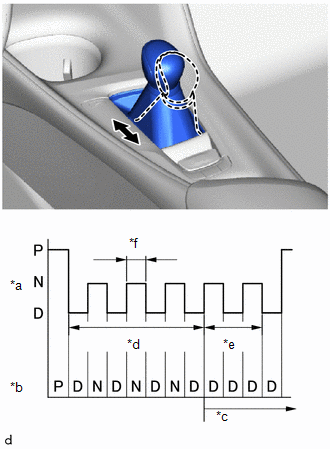
(h) Slowly move the shift lever from P to D, and then back to P (keep the shift lever in each position for approximately 3 seconds).
HINT:
Slowly move the shift lever to circulate the fluid through each part of the continuously variable transaxle assembly.
|
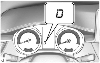
(i) While observing the D shift indicator on the combination meter, move the shift lever back and forth between N and D at an interval of less than 1.5 seconds for 6 seconds or more. NOTICE: Do not pause for 1.5 seconds or more. HINT: Performing this operation will cause the vehicle to enter fluid temperature detection mode. |
|
|
(j) Check that the D shift indicator comes on for 2 seconds. HINT:
|
|
(k) Move the shift lever to P.
(l) Release the brake pedal.
(m) According to the display on the Techstream, perform the Active Test "Connect the TC and TE1 / OFF".
NOTICE:
Make sure that terminals are not connected. If the terminals are connected, the fluid level cannot be precisely adjusted due to fluctuations in engine speed.
HINT:
- Disconnecting the terminals activates engine idle speed control mode.
- In engine idle speed control mode, engine idle speed control starts when the fluid temperature reaches the specified temperature and the engine speed is maintained.
- Even after the terminals are disconnected, fluid temperature detection mode remains active until the ignition switch is turned off.
(n) Adjust the fluid temperature to the fluid level adjustment temperature.
(1) Check the fluid temperature by monitoring the D shift indicator.
Relationship between Fluid Level Adjustment Temperature and the D Shift Indicator:
|
Below Fluid Level Adjustment Temperature |
Fluid Level Adjustment Temperature |
Above Fluid Level Adjustment Temperature |
|
|---|---|---|---|
|
Fluid Temperature ("A/T Oil Temperature 1" displayed on the Techstream) |
35°C (95°F) or less |
35 to 45°C (95 to 113°F) |
45°C (113°F) or more |
|
D Shift Indicator |
Off |
On |
Blinks |
HINT:
- In fluid temperature detection mode, the D shift indicator comes on, goes off, or blinks depending on the fluid temperature.
- The fluid filling procedure should be performed when the D shift indicator is on (the fluid temperature is within the fluid level adjustment temperature range).
(2) If the D shift indicator is on [Fluid Level Adjustment Temperature: 35 to 45°C (95 to 113°F)]: Immediately proceed to the Adjust Fluid Level (Step 9).
(3) Adjust the fluid temperature.
- If the D shift indicator is off [Below Fluid Level Adjustment Temperature: 35°C (95°F) or less]: Warm up the engine with the engine idling in engine idle speed control mode until the D shift indicator turns on.
- If the D shift indicator is on [Fluid Level Adjustment Temperature:35 to 45°C (95 to 113°F)]: Immediately proceed to Adjust Fluid Level (Step 9).
- If the D shift indicator is blinking [Above Fluid Level Adjustment Temperature: 45°C (113°F) or more]: Stop the engine and wait until the fluid temperature drops to 35°C (95°F) or less (the D shift indicator goes off). Then perform the adjust fluid temperature procedure again from the beginning.
7. ADJUST FLUID TEMPERATURE (when Not Using the Techstream)
|
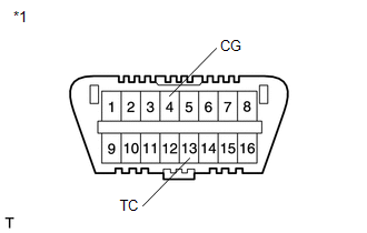
(a) Using SST, connect terminals 13 (TC) and 4 (CG) of the DLC3 with the ignition switch off. SST: 09843-18040 |
|
(b) Depress and hold the brake pedal.
(c) Start the engine.
NOTICE:
To reduce load, make sure that all electrical systems, such as the air conditioning, lighting system, electric fan and audio system, are off.
(d) Slowly move the shift lever from P to D, and then back to P (keep the shift lever in each position for approximately 3 seconds).
HINT:
Slowly move the shift lever to circulate the fluid through each part of the continuously variable transaxle assembly.
|
(e) While observing the D shift indicator on the combination meter, move the shift lever back and forth between N and D at an interval of less than 1.5 seconds for 6 seconds or more. NOTICE: Do not pause for 1.5 seconds or more. HINT: Performing this operation will cause the vehicle to enter fluid temperature detection mode. |
|

|
(f) Check that the D shift indicator comes on for 2 seconds. HINT:
|
|
(g) Move the shift lever to P.
(h) Release the brake pedal.
(i) Remove SST from terminals 13 (TC) and 4 (CG).
NOTICE:
Make sure that the terminals are not connected. If the terminals are connected, the fluid level cannot be precisely adjusted due to fluctuations in engine speed.
HINT:
- Disconnecting the terminals activates engine idle speed control mode.
- In engine idle speed control mode, engine idle speed control starts when the fluid temperature reaches the specified temperature and the engine speed is maintained.
- Even after the terminals are disconnected, fluid temperature detection mode is active until the ignition switch is turned off.
(j) Adjust the fluid temperature to the fluid level adjustment temperature.
(1) Check the fluid temperature by monitoring the D shift indicator.
Relationship between Fluid Level Adjustment Temperature and the D Shift Indicator:
|
Below Fluid Level Adjustment Temperature |
Fluid Level Adjustment Temperature |
Above Fluid Level Adjustment Temperature |
|
|---|---|---|---|
|
Fluid Temperature ("A/T Oil Temperature 1" displayed on the Techstream) |
35°C (95°F) or less |
35 to 45°C (95 to 113°F) |
45°C (113°F) or more |
|
D Shift Indicator |
Off |
On |
Blinks |
HINT:
- In fluid temperature detection mode, the D shift indicator comes on, goes off, or blinks depending on the fluid temperature.
- The fluid filling procedure should be performed when the D shift indicator is on (the fluid temperature is within the fluid level adjustment temperature range).
(2) If the D shift indicator is on [Fluid Level Adjustment Temperature: 35 to 45°C (95 to 113°F)]: Immediately proceed to the Adjust Fluid Level (Step 9).
(3) Adjust the fluid temperature.
- If the D shift indicator is off [Below Fluid Level Adjustment Temperature: 35°C (95°F) or less]: Warm up the engine with the engine idling in engine idle speed control mode until the D shift indicator turns on.
- If the D shift indicator is on [Fluid Level Adjustment Temperature: 35 to 45°C (95 to 113°F)]: Immediately proceed to Adjust Fluid Level (Step 9).
- If the D shift indicator is blinking [Above Fluid Level Adjustment Temperature: 45°C (113°F) or more]: Stop the engine and wait until the fluid temperature drops to 35°C (95°F) or less (the D shift indicator goes off). Then perform the adjust fluid temperature procedure again from the beginning.
8. ADJUST FLUID LEVEL
CAUTION:
Use caution, as the fluid is hot while the engine is idling and the radiator fan is operating.
(a) Lift the vehicle.
NOTICE:
Set the vehicle on a lift so that the vehicle is kept level when it is lifted up (make sure that the tilt angle from the front to rear of the vehicle is within +/-1°).
|
(b) Using a 6 mm hexagon socket wrench, remove the overflow plug and gasket from the transaxle oil (CVT) pan sub-assembly. CAUTION: Be careful as the fluid coming out of the overflow plug hole is hot. |
|
(c) Check the amount of fluid that comes out of the overflow plug hole.
NOTICE:
If only a small amount of fluid (approximately 5 cc (0.3 cu. in.)) comes out of the overflow plug hole, then only fluid remaining in the No. 1 transmission oil filler tube has come out. This is not considered to be overflow.
- If the amount of fluid that comes out of the overflow plug hole is large, proceed to *1.
- If no fluid comes out of the overflow plug hole, proceed to *2.
|
(d) *1: If the amount of fluid that comes out of the overflow plug hole is large, wait until the fluid flow slows and only drips come out. HINT: The fluid flow will not stop completely because the fluid continues to expand as its temperature increases. |
|
|
(e) *2: If no fluid comes out of the overflow plug hole, remove the refill plug and gasket. Then add fluid through the refill hole until fluid comes out of the overflow plug hole. Wait until the fluid flow slows and only drips come out. NOTICE: Use Toyota Genuine CVT fluid FE. |
|
|
(f) Using a 6 mm hexagon socket wrench, install a new gasket and the overflow plug to the transaxle oil (CVT) pan sub-assembly. Torque: 40 N·m {408 kgf·cm, 30 ft·lbf} |
|
|
(g) Install a new gasket and the refill plug to the continuously variable transaxle assembly. Torque: 49 N·m {500 kgf·cm, 36 ft·lbf} |
|
(h) Lower the vehicle.
(i) Turn the ignition switch off.
HINT:
Turning the ignition switch off exits fluid temperature detection mode.
(j) Remove the Techstream from the DLC3 (when using the Techstream).
9. PERFORM ATF THERMAL DEGRADATION ESTIMATE RESET
NOTICE:
If approximately 50% or more of the CVT fluid has been replaced during a repair of the transaxle or a similar operation, perform ATF Thermal Degradation Estimate Reset.
Click here
10. REBUILD WORK
(a) Lift the vehicle.
(b) Clean each part.
(c) Check for fluid leaks.
(d) Install the rear engine under cover LH.
Click here
(e) Install the No. 1 engine under cover.
Click here
(f) Lower the vehicle.
 Replacement
REPLACEMENT
CAUTION / NOTICE / HINT
Click here
...

Other materials:
Toyota CH-R Service Manual > Navigation System: Satellite Radio Broadcast cannot be Received
CAUTION / NOTICE / HINT
NOTICE:
Some satellite radio broadcasts require payment. A contract must be made between
a satellite radio company and the user. If the contract expires, it will not be
possible to listen to the broadcast.
WIRING DIAGRAM
PROCEDURE
1.
CHECK ...
Toyota CH-R Service Manual > Continuously Variable Transaxle System: Transmission Fluid Temperature Sensor "A" Circuit Low Input (P0712,P0713)
DESCRIPTION
The CVT fluid temperature sensor converts the fluid temperature into a resistance
value which is detected by the ECM.
The sensor resistance changes with the CVT fluid temperature. As the temperature
rises, the sensor resistance decreases. The ECM applies voltage to the temperature ...
Toyota C-HR (AX20) 2023-2026 Owner's Manual
Toyota CH-R Owners Manual
- For safety and security
- Instrument cluster
- Operation of each component
- Driving
- Interior features
- Maintenance and care
- When trouble arises
- Vehicle specifications
- For owners
Toyota CH-R Service Manual
- Introduction
- Maintenance
- Audio / Video
- Cellular Communication
- Navigation / Multi Info Display
- Park Assist / Monitoring
- Brake (front)
- Brake (rear)
- Brake Control / Dynamic Control Systems
- Brake System (other)
- Parking Brake
- Axle And Differential
- Drive Shaft / Propeller Shaft
- K114 Cvt
- 3zr-fae Battery / Charging
- Networking
- Power Distribution
- Power Assist Systems
- Steering Column
- Steering Gear / Linkage
- Alignment / Handling Diagnosis
- Front Suspension
- Rear Suspension
- Tire / Wheel
- Tire Pressure Monitoring
- Door / Hatch
- Exterior Panels / Trim
- Horn
- Lighting (ext)
- Mirror (ext)
- Window / Glass
- Wiper / Washer
- Door Lock
- Heating / Air Conditioning
- Interior Panels / Trim
- Lighting (int)
- Meter / Gauge / Display
- Mirror (int)
- Power Outlets (int)
- Pre-collision
- Seat
- Seat Belt
- Supplemental Restraint Systems
- Theft Deterrent / Keyless Entry

0.0113