Toyota CH-R Service Manual: Replacement
REPLACEMENT
CAUTION / NOTICE / HINT
The necessary procedures (adjustment, calibration, initialization, or registration) that must be performed after parts are removed, installed, or replaced during the CVT fluid replacement are shown below.
Necessary Procedure After Parts Removed/Installed/Replaced|
Replacement Part or Procedure |
Necessary Procedure |
Effect/Inoperative when not Performed |
Link |
|---|---|---|---|
|
Replacement of CVT fluid |
ATF thermal degradation estimate reset |
The value of the Data List item "ATF Thermal Degradation Estimate" is not estimated correctly |
|
PROCEDURE
1. REPLACE CONTINUOUSLY VARIABLE TRANSAXLE FLUID
(a) Lift the vehicle. [*1]
NOTICE:
Set the vehicle on a lift so that the vehicle is kept level when it is lifted up (make sure that the tilt angle from the front to rear of the vehicle is within +/-1°).
(b) Remove the No. 1 engine under cover.
Click here
.gif)
(c) Remove the rear engine under cover LH.
Click here
|
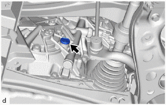
(d) Remove the refill plug and gasket from the continuously variable transaxle assembly. [*2] |
|
|
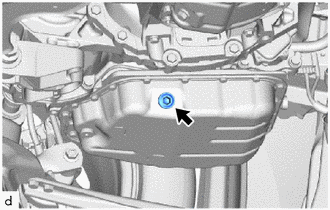
(e) Using a 10 mm hexagon socket wrench, remove the drain plug and gasket from the transaxle oil (CVT) pan sub-assembly. [*3] |
|
|
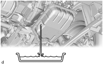
(f) Measure the amount of fluid drained. [*4] HINT: Add the same amount of fluid in step [*6]. |
|
|
(g) Using a 10 mm hexagon socket wrench, temporarily install the gasket and drain plug to the transaxle oil (CVT) pan sub-assembly. [*5] HINT: Reuse the old gasket as the drain plug will be removed again when flushing the CVT fluid. |
|
|
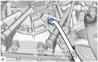
(h) Add fluid to the refill hole using the same amount of fluid drained in step [*4]. [*6] NOTICE: Use Toyota Genuine CVT fluid FE. |
|
|
(i) Temporarily install the gasket and refill plug to the continuously variable transaxle assembly. [*7] HINT: Reuse the old gasket as the refill plug will be removed again when flushing the CVT fluid. |
|
(j) Lower the vehicle. [*8]
(k) Start the engine. [*9]
(l) Slowly move the shift lever from P to D, and then back to P (keep the shift lever in each position for approximately 3 seconds). [*10]
HINT:
Slowly move the shift lever to circulate the fluid through each part of the continuously variable transaxle assembly.
(m) Allow the engine assembly to idle for 30 seconds to warm it up. [*11]
(n) Turn the ignition switch off. [*12]
(o) Repeat steps [*1] to [*12].
(p) Repeat steps [*1] to [*12].
|
(q) Using a 10 mm hexagon socket wrench, install a new gasket and the drain plug to the transaxle oil (CVT) pan sub-assembly. Torque: 49 N·m {500 kgf·cm, 36 ft·lbf} |
|
2. ADD SPECIFIED AMOUNT OF FLUID
Click here
3. ADJUST FLUID TEMPERATURE (when Using the Techstream)
Click here
4. ADJUST FLUID TEMPERATURE (when Not Using the Techstream)
Click here
5. ADJUST FLUID LEVEL
Click here
6. PERFORM ATF THERMAL DEGRADATION ESTIMATE RESET
NOTICE:
If approximately 50% or more of the CVT fluid has been replaced during a repair of the transaxle or a similar operation, perform ATF Thermal Degradation Estimate Reset.
Click here
7. REBUILD WORK
Click here
 Components
COMPONENTS
ILLUSTRATION
*1
REFILL PLUG
*2
OVERFLOW PLUG
*3
NO. 1 TRANSMISSION OIL FILLER TUBE
*4
DRAIN ...
 Rear Brake Flexible Hose
Components
COMPONENTS
ILLUSTRATION
*1
REAR FLEXIBLE HOSE
*2
GASKET
*3
UNION BOLT
-
-
...
Other materials:
Toyota CH-R Service Manual > Front Door Outside Moulding: Reassembly
REASSEMBLY
CAUTION / NOTICE / HINT
HINT:
Use the same procedure for the RH and LH sides.
The procedure listed below is for the LH side.
PROCEDURE
1. INSTALL OUTSIDE MOULDING RETAINER
(a) When using a new front door outside moulding:
(1) Clean the surface of the front door ou ...
Toyota CH-R Service Manual > Windshield Deicer System: Data List / Active Test
DATA LIST / ACTIVE TEST
ACTIVE TEST
HINT:
Using the Techstream to perform Active Tests allows relays, VSVs, actuators and
other items to be operated without removing any parts. This non-intrusive functional
inspection can be very useful because intermittent operation may be discovered before ...
Toyota C-HR (AX20) 2023-2026 Owner's Manual
Toyota CH-R Owners Manual
- For safety and security
- Instrument cluster
- Operation of each component
- Driving
- Interior features
- Maintenance and care
- When trouble arises
- Vehicle specifications
- For owners
Toyota CH-R Service Manual
- Introduction
- Maintenance
- Audio / Video
- Cellular Communication
- Navigation / Multi Info Display
- Park Assist / Monitoring
- Brake (front)
- Brake (rear)
- Brake Control / Dynamic Control Systems
- Brake System (other)
- Parking Brake
- Axle And Differential
- Drive Shaft / Propeller Shaft
- K114 Cvt
- 3zr-fae Battery / Charging
- Networking
- Power Distribution
- Power Assist Systems
- Steering Column
- Steering Gear / Linkage
- Alignment / Handling Diagnosis
- Front Suspension
- Rear Suspension
- Tire / Wheel
- Tire Pressure Monitoring
- Door / Hatch
- Exterior Panels / Trim
- Horn
- Lighting (ext)
- Mirror (ext)
- Window / Glass
- Wiper / Washer
- Door Lock
- Heating / Air Conditioning
- Interior Panels / Trim
- Lighting (int)
- Meter / Gauge / Display
- Mirror (int)
- Power Outlets (int)
- Pre-collision
- Seat
- Seat Belt
- Supplemental Restraint Systems
- Theft Deterrent / Keyless Entry

0.0953