Toyota CH-R Service Manual: Rear Brake Flexible Hose
Components
COMPONENTS
ILLUSTRATION
|
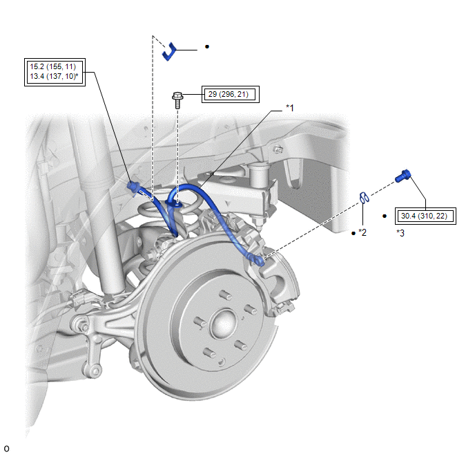
*1 |
REAR FLEXIBLE HOSE |
*2 |
GASKET |
|
*3 |
UNION BOLT |
- |
- |
.png) |
Tightening torque for "Major areas involving basic vehicle performance such as moving/turning/stopping" : N*m (kgf*cm, ft.*lbf) |
* |
For use with a union nut wrench |
|
● |
Non-reusable part |
- |
- |
Removal
REMOVAL
CAUTION / NOTICE / HINT
HINT:
- Use the same procedure for the RH side and LH side.
- The following procedure is for the LH side.
PROCEDURE
1. REMOVE REAR WHEEL
Click here
.gif)
2. DRAIN BRAKE FLUID
NOTICE:
If brake fluid leaks onto any painted surface, immediately wash it off.
3. REMOVE REAR FLEXIBLE HOSE
|
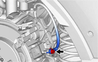
(a) Remove the union bolt and gasket, and disconnect the rear flexible hose from the rear disc brake cylinder assembly. |
|
|
(b) Remove the bolt and separate the rear flexible hose from the flexible hose bracket. |
|
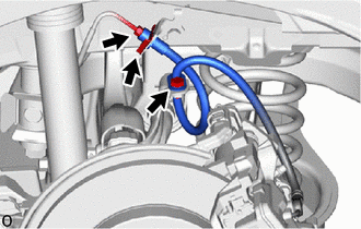
(c) Using a union nut wrench, disconnect the brake tube while holding the rear flexible hose from the brake tube with a wrench.
NOTICE:
- Do not kink or damage the brake tube.
- Do not allow any foreign matter such as dirt or dust to enter the brake tube from the connecting parts.
(d) Remove the clip and rear flexible hose from the vehicle body.
Installation
INSTALLATION
CAUTION / NOTICE / HINT
NOTICE:
When reusing the rear flexible hoses, use the identification marks created during removal to install each rear flexible hose to its original position.
HINT:
- Use the same procedure for the RH side and LH side.
- The following procedure is for the LH side.
PROCEDURE
1. INSTALL REAR FLEXIBLE HOSE
NOTICE:
When installing the rear flexible hose, minimize twisting of the hose.
|
(a) Install the rear flexible hose to the vehicle body with a new clip. NOTICE: Install the clip as far as it will go. |
|
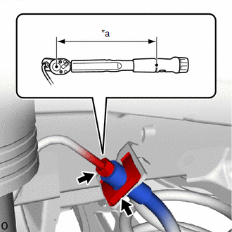
(b) Using a union nut wrench, connect the brake tube to the rear flexible hose while holding the rear flexible hose to the brake tube with a wrench.
Torque:
Specified tightening torque :
15.2 N·m {155 kgf·cm, 11 ft·lbf}
NOTICE:
- Do not kink or damage the brake tube.
- Do not allow any foreign matter such as dirt or dust to enter the brake tube from the connecting parts.
HINT:
- Calculate the torque wrench reading when changing the fulcrum length
of the torque wrench.
Click here
.gif)
- When using a union nut wrench (fulcrum length of 22 mm (0.866 in.)) + torque wrench (fulcrum length of 162 mm (6.38 in.)): 13.4 N*m (137 kgf*cm, 10 ft.*lbf)
(c) Install the rear flexible hose to the flexible hose bracket with the bolt.
Torque:
29 N·m {296 kgf·cm, 21 ft·lbf}
(d) Install the rear flexible hose to the rear disc brake cylinder assembly with a new union bolt and a new gasket.
Torque:
30.4 N·m {310 kgf·cm, 22 ft·lbf}
NOTICE:
Install the rear flexible hose lock securely into the lock hole in the rear disc brake cylinder assembly.
2. BLEED BRAKE LINE
Click here
3. INSTALL REAR WHEEL
Click here
 Replacement
REPLACEMENT
CAUTION / NOTICE / HINT
The necessary procedures (adjustment, calibration, initialization, or registration)
that must be performed after parts are removed, installed, or replaced durin ...

Other materials:
Toyota CH-R Service Manual > Can Communication System: ECU Malfunction (B1003)
DESCRIPTION
DTC No.
Detection Item
DTC Detection Condition
Trouble Area
Note
B1003
ECU Malfunction
A malfunction in the non-volatile storage of the central gateway ECU
(network gateway ECU) is detected ...
Toyota CH-R Owners Manual > Operation of each component: Key information
The keys
The following keys are provided with the vehicle.
Vehicles without a smart key system (type A)
Key (with a wireless remote control function)
Operating the wireless remote control function
Key (without a wireless remote control function)
Key number plate
Vehicles without a ...
Toyota C-HR (AX20) 2023-2026 Owner's Manual
Toyota CH-R Owners Manual
- For safety and security
- Instrument cluster
- Operation of each component
- Driving
- Interior features
- Maintenance and care
- When trouble arises
- Vehicle specifications
- For owners
Toyota CH-R Service Manual
- Introduction
- Maintenance
- Audio / Video
- Cellular Communication
- Navigation / Multi Info Display
- Park Assist / Monitoring
- Brake (front)
- Brake (rear)
- Brake Control / Dynamic Control Systems
- Brake System (other)
- Parking Brake
- Axle And Differential
- Drive Shaft / Propeller Shaft
- K114 Cvt
- 3zr-fae Battery / Charging
- Networking
- Power Distribution
- Power Assist Systems
- Steering Column
- Steering Gear / Linkage
- Alignment / Handling Diagnosis
- Front Suspension
- Rear Suspension
- Tire / Wheel
- Tire Pressure Monitoring
- Door / Hatch
- Exterior Panels / Trim
- Horn
- Lighting (ext)
- Mirror (ext)
- Window / Glass
- Wiper / Washer
- Door Lock
- Heating / Air Conditioning
- Interior Panels / Trim
- Lighting (int)
- Meter / Gauge / Display
- Mirror (int)
- Power Outlets (int)
- Pre-collision
- Seat
- Seat Belt
- Supplemental Restraint Systems
- Theft Deterrent / Keyless Entry

0.0111