Toyota CH-R Service Manual: Key Reminder Buzzer does not Sound
DESCRIPTION
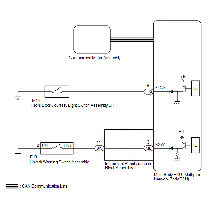
The key reminder warning buzzer sounds when the driver door is opened while the ignition switch is off or ACC. The key reminder warning buzzer is activated when the main body ECU (multiplex network body ECU) sends an unlock warning switch signal and driver door courtesy light switch signal to the combination meter assembly via CAN communication.
WIRING DIAGRAM
CAUTION / NOTICE / HINT
NOTICE:
- The key reminder warning system uses the CAN communication system. Inspect
the communication function by following How to Proceed with Troubleshooting.
Troubleshoot the key reminder warning system after confirming that the communication
systems are functioning properly.
Click here
.gif)
- When replacing the combination meter assembly, always replace it with a new one. If a combination meter assembly which was installed to another vehicle is used, the information stored in it will not match the information from the vehicle and a DTC may be stored.
PROCEDURE
|
1. |
CHECK COMBINATION METER ASSEMBLY (BUZZER OPERATION) |
(a) Turn the ignition switch to ON. Place luggage on the front passenger seat to cause the seat belt warning light to blink.
(b) When driving the vehicle at 20 km/h (12 mph) or higher, check that the seat belt warning buzzer sounds to inform that the front passenger seat belt is not fastened.
HINT:
The key reminder warning system sounds the buzzer built into the combination meter assembly as a key reminder warning. This buzzer is also used for the seat belt warning system. Therefore, check the operation of the combination meter buzzer by checking if the buzzer sounds to inform that the seat belt is not fastened.
OK:
Combination meter buzzer sounds.
| NG | .gif) |
REPLACE COMBINATION METER ASSEMBLY |
|
.gif)
|
2. |
READ VALUE USING TECHSTREAM (FL Door Courtesy SW) |
(a) Connect the Techstream to the DLC3.
(b) Turn the ignition switch to ON.
(c) Turn the Techstream on.
(d) Enter the following menus: Body Electrical / Main Body / Data List.
(e) Read the Data List according to the display on the Techstream.
Body Electrical > Main Body > Data List|
Tester Display |
Measurement Item |
Range |
Normal Condition |
Diagnostic Note |
|---|---|---|---|---|
|
FL Door Courtesy SW |
Front door courtesy light switch assembly LH signal |
OFF or ON |
OFF: Front door LH closed ON: Front door LH open |
- |
|
Tester Display |
|---|
|
FL Door Courtesy SW |
OK:
The Techstream indicates ON or OFF according to the driver door conditions shown in the table.
| NG | |
GO TO STEP 7 |
|
|
3. |
READ VALUE USING TECHSTREAM (Key Unlock Warning SW) |
(a) Connect the Techstream to the DLC3.
(b) Turn the ignition switch to ON.
(c) Turn the Techstream on.
(d) Enter the following menus: Body Electrical / Main Body / Data List.
(e) Read the Data List according to the display on the Techstream.
Body Electrical > Main Body > Data List|
Tester Display |
Measurement Item |
Range |
Normal Condition |
Diagnostic Note |
|---|---|---|---|---|
|
Key Unlock Warning SW |
Unlock warning switch signal |
OFF or ON |
OFF: No key in ignition key cylinder ON: Key in ignition key cylinder |
- |
|
Tester Display |
|---|
|
Key Unlock Warning SW |
OK:
The Techstream indicates ON or OFF according to whether the key is in the ignition key cylinder.
| OK | |
REPLACE MAIN BODY ECU (MULTIPLEX NETWORK BODY ECU)
|
|
|
4. |
INSPECT UNLOCK WARNING SWITCH ASSEMBLY |
(a) Remove the unlock warning switch assembly.
Click here
(b) Inspect the unlock warning switch assembly.
Click here
| NG | |
REPLACE UNLOCK WARNING SWITCH ASSEMBLY |
|
|
5. |
CHECK HARNESS AND CONNECTOR (UNLOCK WARNING SWITCH ASSEMBLY - INSTRUMENT PANEL JUNCTION BLOCK ASSEMBLY) |
(a) Disconnect the F13 unlock warning switch assembly connector.
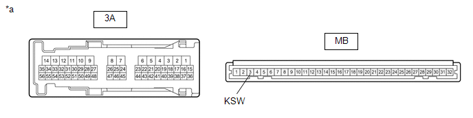
(b) Disconnect the 3A instrument panel junction block assembly connector.
(c) Measure the resistance according to the value(s) in the table below.
Standard Resistance:
|
Tester Connection |
Condition |
Specified Condition |
|---|---|---|
|
F13-1 (UN+) - 3A-41 |
Always |
Below 1 Ω |
|
F13-2 (UN-) - Body ground |
Always |
Below 1 Ω |
|
F13-1 (UN+) or 3A-41 - Body ground |
Always |
10 kΩ or higher |
| NG | |
REPAIR OR REPLACE HARNESS OR CONNECTOR |
|
|
6. |
INSPECT INSTRUMENT PANEL JUNCTION BLOCK ASSEMBLY |
(a) Remove the instrument panel junction block assembly.
Click here
|
*a |
Component without harness connected (Instrument Panel Junction Block Assembly) |
- |
- |
(b) Remove the main body ECU (multiplex network body ECU) from the instrument panel junction block assembly.
(c) Measure the resistance according to the value(s) in the table below.
Standard Resistance:
|
Tester Connection |
Condition |
Specified Condition |
|---|---|---|
|
3A-41 - MB-3 (KSW) |
Always |
Below 1 Ω |
| OK | |
REPLACE MAIN BODY ECU (MULTIPLEX NETWORK BODY ECU)
|
| NG | |
REPLACE INSTRUMENT PANEL JUNCTION BLOCK ASSEMBLY
|
|
7. |
INSPECT FRONT DOOR COURTESY LIGHT SWITCH ASSEMBLY LH |
(a) Remove the front door courtesy light switch assembly LH.
Click here
(b) Inspect the front door courtesy light switch assembly LH.
Click here
| NG | |
REPLACE FRONT DOOR COURTESY LIGHT SWITCH ASSEMBLY LH
|
|
|
8. |
CHECK HARNESS AND CONNECTOR (FRONT DOOR COURTESY LIGHT SWITCH ASSEMBLY LH - MAIN BODY ECU (MULTIPLEX NETWORK BODY ECU)) |
(a) Disconnect the M11 front door courtesy light switch assembly LH connector.
(b) Disconnect the F15 main body ECU (multiplex network body ECU) connector.
(c) Measure the resistance according to the value(s) in the table below.
Standard Resistance:
|
Tester Connection |
Condition |
Specified Condition |
|---|---|---|
|
M11-1 - F15-6 (FLCY) |
Always |
Below 1 Ω |
|
M11-1 or F15-6 (FLCY) - Body ground |
Always |
10 kΩ or higher |
| OK | |
REPLACE MAIN BODY ECU (MULTIPLEX NETWORK BODY ECU)
|
| NG | |
REPAIR OR REPLACE HARNESS OR CONNECTOR |
 Data List / Active Test
DATA LIST / ACTIVE TEST
DATA LIST
HINT:
Using the Techstream to read the Data List allows the values or states of switches,
sensors, actuators and other items to be read without removing any part ...

Other materials:
Toyota CH-R Service Manual > Brake Actuator: Precaution
PRECAUTION
IGNITION SWITCH EXPRESSIONS
(a) The type of ignition switch used on this model differs depending on the specifications
of the vehicle. The expressions listed in the table below are used in this section.
Expression
Ignition Switch (Position)
Engine Swi ...
Toyota CH-R Service Manual > Lighting (ext): Rear Side Marker Light Bulb
Components
COMPONENTS
ILLUSTRATION
*1
REAR COMBINATION LIGHT ASSEMBLY
*2
REAR COMBINATION LIGHT COVER
*3
REAR SIDE MARKER LIGHT BULB
*4
REAR COMBINATION LIGHT SOCKET AND WIRE
Removal
REM ...
Toyota C-HR (AX20) 2023-2026 Owner's Manual
Toyota CH-R Owners Manual
- For safety and security
- Instrument cluster
- Operation of each component
- Driving
- Interior features
- Maintenance and care
- When trouble arises
- Vehicle specifications
- For owners
Toyota CH-R Service Manual
- Introduction
- Maintenance
- Audio / Video
- Cellular Communication
- Navigation / Multi Info Display
- Park Assist / Monitoring
- Brake (front)
- Brake (rear)
- Brake Control / Dynamic Control Systems
- Brake System (other)
- Parking Brake
- Axle And Differential
- Drive Shaft / Propeller Shaft
- K114 Cvt
- 3zr-fae Battery / Charging
- Networking
- Power Distribution
- Power Assist Systems
- Steering Column
- Steering Gear / Linkage
- Alignment / Handling Diagnosis
- Front Suspension
- Rear Suspension
- Tire / Wheel
- Tire Pressure Monitoring
- Door / Hatch
- Exterior Panels / Trim
- Horn
- Lighting (ext)
- Mirror (ext)
- Window / Glass
- Wiper / Washer
- Door Lock
- Heating / Air Conditioning
- Interior Panels / Trim
- Lighting (int)
- Meter / Gauge / Display
- Mirror (int)
- Power Outlets (int)
- Pre-collision
- Seat
- Seat Belt
- Supplemental Restraint Systems
- Theft Deterrent / Keyless Entry

0.0087