Toyota CH-R Service Manual: Precaution
PRECAUTION
IGNITION SWITCH EXPRESSIONS
(a) The type of ignition switch used on this model differs according to the specifications of the vehicle. The expressions listed in the table below are used in this section.
|
Expression |
Ignition Switch (Position) |
Engine Switch (Condition) |
|---|---|---|
|
Ignition Switch off |
LOCK |
Off (Lock) |
|
Ignition Switch ACC |
ACC |
On (ACC) |
|
Ignition Switch ON |
ON |
On (IG) |
|
Engine Start |
START |
On (Start) |
TROUBLESHOOTING PRECAUTIONS
(a) When inspecting the rear brakes, disconnect the connector of the parking brake actuator assembly or disconnect the cable from the negative (-) battery terminal.
CAUTION:
- Do not perform the rear brake inspection while either the parking brake
actuator assembly connector or the negative (-) battery terminal are connected.
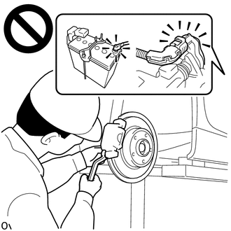
- The rear disc brake piston could operate, resulting in an accident such as hands being caught.
(b) The electric parking brake may still operate up to 20 seconds after the ignition switch is turned off. Before disconnecting connectors or fuses, turn the ignition switch off and wait 20 seconds or more.
(c) If a component has been removed and installed, confirm that the system operates normally by checking for DTCs after installation has been completed.
HANDLING PRECAUTIONS
(a) When tilting the vehicle to perform work after parking the vehicle on a level surface, the braking force may not be sufficient. Make sure to pull the electric parking brake switch (electric parking brake switch assembly) to the lock side 2 times (2 lock operations).
HINT:
- The electric parking brake system determines the amount of force used to operate the parking brake according to the tilt angle detected by the deceleration sensor (airbag sensor assembly).
- When the parking brake indicator (red) is illuminated after the electric parking brake switch (electric parking brake switch assembly) has been pulled to the lock side, the maximum amount of braking force is applied if the electric parking brake switch (electric parking brake switch assembly) is pulled to the lock side one more time.
(b) The parking brake indicator light blinks (red) when the ignition switch is turned to ON after replacing the skid control ECU (brake actuator assembly). Operate the electric parking brake switch (electric parking brake switch assembly) to turn off the parking brake indicator light.
PRECAUTIONS FOR TOWING VEHICLES
(a) For towing precautions: Click here
.gif)
PARKING BRAKE FORCED RELEASE METHOD
(a) For the parking brake forced release method.
- for TMC Made
Click here
- for TMMT Made
Click here

 Parts Location
PARTS LOCATION
ILLUSTRATION
*1
SKID CONTROL ECU (BRAKE ACTUATOR ASSEMBLY)
*2
ECM
*3
NO. 1 ENGINE ROOM RELAY BLOCK
- ABS-M ...
Other materials:
Toyota CH-R Service Manual > Can Communication System: Check Bus 3 Line for Short to +B
DESCRIPTION
There may be a short circuit between one of the CAN bus lines and +B when no
resistance exists between terminal 6 (CA3H) of the central gateway ECU (network
gateway ECU) and terminal 16 (BAT) of the DLC3, or terminal 21 (CA3L) of the central
gateway ECU (network gateway ECU) and t ...
Toyota CH-R Service Manual > Shift Lever: Disassembly
DISASSEMBLY
PROCEDURE
1. REMOVE SHIFTING HOLE COVER SUB-ASSEMBLY
(a) Disengage the 4 guides and 6 claws to remove the shifting hole cover
sub-assembly from the upper console panel sub-assembly.
2. REMOVE SHIFT POSITION INDICATOR
...
Toyota C-HR (AX20) 2023-2026 Owner's Manual
Toyota CH-R Owners Manual
- For safety and security
- Instrument cluster
- Operation of each component
- Driving
- Interior features
- Maintenance and care
- When trouble arises
- Vehicle specifications
- For owners
Toyota CH-R Service Manual
- Introduction
- Maintenance
- Audio / Video
- Cellular Communication
- Navigation / Multi Info Display
- Park Assist / Monitoring
- Brake (front)
- Brake (rear)
- Brake Control / Dynamic Control Systems
- Brake System (other)
- Parking Brake
- Axle And Differential
- Drive Shaft / Propeller Shaft
- K114 Cvt
- 3zr-fae Battery / Charging
- Networking
- Power Distribution
- Power Assist Systems
- Steering Column
- Steering Gear / Linkage
- Alignment / Handling Diagnosis
- Front Suspension
- Rear Suspension
- Tire / Wheel
- Tire Pressure Monitoring
- Door / Hatch
- Exterior Panels / Trim
- Horn
- Lighting (ext)
- Mirror (ext)
- Window / Glass
- Wiper / Washer
- Door Lock
- Heating / Air Conditioning
- Interior Panels / Trim
- Lighting (int)
- Meter / Gauge / Display
- Mirror (int)
- Power Outlets (int)
- Pre-collision
- Seat
- Seat Belt
- Supplemental Restraint Systems
- Theft Deterrent / Keyless Entry

0.0077