Toyota CH-R Service Manual: Parts Location
PARTS LOCATION
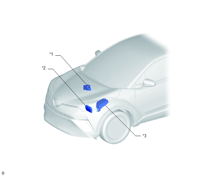
ILLUSTRATION
|
*1 |
SKID CONTROL ECU (BRAKE ACTUATOR ASSEMBLY) |
*2 |
ECM |
|
*3 |
NO. 1 ENGINE ROOM RELAY BLOCK - ABS-MAIN FUSE - ECU-IG1 NO. 2 FUSE |
- |
- |
ILLUSTRATION
|
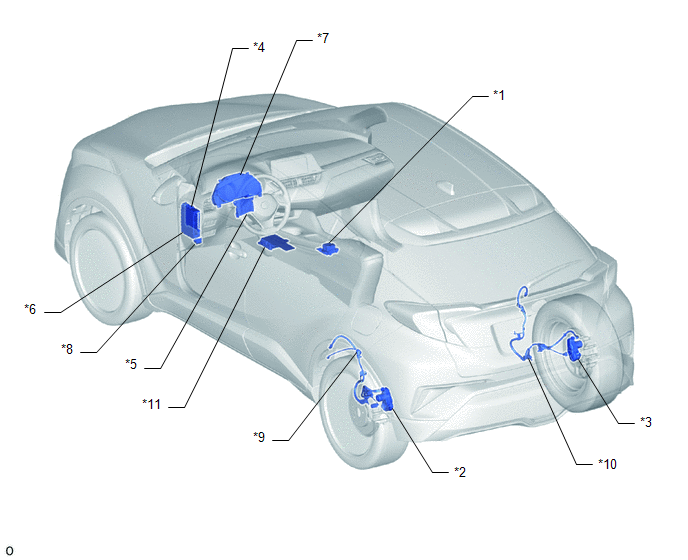
*1 |
ELECTRIC PARKING BRAKE SWITCH (ELECTRIC PARKING BRAKE SWITCH ASSEMBLY) |
*2 |
PARKING BRAKE ACTUATOR ASSEMBLY LH |
|
*3 |
PARKING BRAKE ACTUATOR ASSEMBLY RH |
*4 |
MAIN BODY ECU (MULTIPLEX NETWORK BODY ECU) |
|
*5 |
AIR CONDITIONING AMPLIFIER ASSEMBLY |
*6 |
INSTRUMENT PANEL JUNCTION BLOCK ASSEMBLY - ECU-B NO. 2 FUSE |
|
*7 |
COMBINATION METER ASSEMBLY |
*8 |
DLC3 |
|
*9 |
NO. 2 PARKING BRAKE WIRE ASSEMBLY |
*10 |
NO. 1 PARKING BRAKE WIRE ASSEMBLY |
|
*11 |
DECELERATION SENSOR (AIRBAG SENSOR ASSEMBLY) |
- |
- |
 Precaution
PRECAUTION
IGNITION SWITCH EXPRESSIONS
(a) The type of ignition switch used on this model differs according to the specifications
of the vehicle. The expressions listed in the table below are used ...
 System Diagram
SYSTEM DIAGRAM
...
Other materials:
Toyota CH-R Service Manual > Side Airbag Sensor(for Center Pillar): Components
COMPONENTS
ILLUSTRATION
*A
w/ Rear Seat Side Airbag
*B
w/o Rear Seat Side Airbag
*1
CENTER PILLAR LOWER GARNISH
*2
FLOOR SIDE AIRBAG SENSOR
*3
FRONT DOOR OPENING TRIM WEATHER ...
Toyota CH-R Service Manual > Lighting System: High Beam Headlight Circuit
DESCRIPTION
The main body ECU (multiplex network body ECU) controls the high beam headlights.
WIRING DIAGRAM
CAUTION / NOTICE / HINT
NOTICE:
Inspect the fuse for circuits related to this system before performing
the following procedure.
Check the operation of the low beam head ...
Toyota C-HR (AX20) 2023-2026 Owner's Manual
Toyota CH-R Owners Manual
- For safety and security
- Instrument cluster
- Operation of each component
- Driving
- Interior features
- Maintenance and care
- When trouble arises
- Vehicle specifications
- For owners
Toyota CH-R Service Manual
- Introduction
- Maintenance
- Audio / Video
- Cellular Communication
- Navigation / Multi Info Display
- Park Assist / Monitoring
- Brake (front)
- Brake (rear)
- Brake Control / Dynamic Control Systems
- Brake System (other)
- Parking Brake
- Axle And Differential
- Drive Shaft / Propeller Shaft
- K114 Cvt
- 3zr-fae Battery / Charging
- Networking
- Power Distribution
- Power Assist Systems
- Steering Column
- Steering Gear / Linkage
- Alignment / Handling Diagnosis
- Front Suspension
- Rear Suspension
- Tire / Wheel
- Tire Pressure Monitoring
- Door / Hatch
- Exterior Panels / Trim
- Horn
- Lighting (ext)
- Mirror (ext)
- Window / Glass
- Wiper / Washer
- Door Lock
- Heating / Air Conditioning
- Interior Panels / Trim
- Lighting (int)
- Meter / Gauge / Display
- Mirror (int)
- Power Outlets (int)
- Pre-collision
- Seat
- Seat Belt
- Supplemental Restraint Systems
- Theft Deterrent / Keyless Entry

0.0083