Toyota CH-R Service Manual: Installation
INSTALLATION
PROCEDURE
1. INSTALL BRAKE PEDAL PAD
(a) Install the brake pedal pad from the brake pedal support assembly.
2. INSTALL BRAKE PEDAL SUPPORT ASSEMBLY
(a) Install the nut to the brake pedal support assembly.
|
(b) Temporarily install the brake pedal support assembly with 2 new clips. |
|
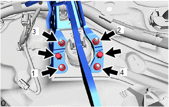
(c) Install the 4 nuts.
Torque:
12.7 N·m {130 kgf·cm, 9 ft·lbf}
NOTICE:
Tighten the nuts in the order shown in the illustration.
(d) Install the brake pedal support assembly to the instrument panel reinforcement assembly with the bolt.
Torque:
23.6 N·m {241 kgf·cm, 17 ft·lbf}
(e) w/ Brake pedal Load Sensing Switch:
(1) Engage the clamp to install the wire harness to the brake pedal support assembly.
(2) Connect the brake pedal load sensing switch connector.
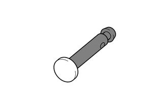
3. INSTALL PUSH ROD PIN
(a) Apply lithium soap base glycol grease to the push rod pin.
.png) |
Lithium Soap Base Glycol Grease |
|
(b) Connect the brake master cylinder push rod clevis to the brake pedal support assembly with the push rod pin, and install a new clip as shown in the illustration. NOTICE: Be sure to install the push rod pin in the correct direction. |
|
.png)
4. INSTALL BRAKE PEDAL RETURN SPRING
(a) Install the brake pedal return spring to the brake pedal support assembly and push rod pin.
5. INSTALL STOP LIGHT SWITCH MOUNTING ADJUSTER
6. INSTALL STOP LIGHT SWITCH ASSEMBLY
Click here
.gif)
7. INSTALL INSTRUMENT PANEL SAFETY PAD SUB-ASSEMBLY
Click here
8. INSPECT AND ADJUST BRAKE PEDAL
Click here
 Adjustment
ADJUSTMENT
PROCEDURE
1. INSPECT AND ADJUST BRAKE PEDAL HEIGHT
(a) Remove the No. 1 air duct.
Click here
(b) Check the brake pedal height.
NOTICE:
Inspect and adjust the brake pedal ...
 Brake System
...
Other materials:
Toyota CH-R Service Manual > Washer Level Warning Switch: Removal
REMOVAL
PROCEDURE
1. REMOVE FRONT WHEEL RH
Click here
2. REMOVE ROCKER PANEL MOULDING RH
Click here
3. REMOVE FRONT FENDER MOULDING SUB-ASSEMBLY RH
Click here
4. REMOVE FRONT WHEEL OPENING EXTENSION PAD RH
Click here
5. REMOVE FRONT FENDER LINER RH
Click here
6. DRA ...
Toyota CH-R Service Manual > Door / Hatch: Back Door Weatherstrip
Components
COMPONENTS
ILLUSTRATION
*1
BACK DOOR WEATHERSTRIP
-
-
●
Non-reusable part
-
-
Removal
REMOVAL
PROCEDURE
1. REMOVE BACK DOOR WEATHERSTRIP
(a) Remove the back do ...
Toyota C-HR (AX20) 2023-2026 Owner's Manual
Toyota CH-R Owners Manual
- For safety and security
- Instrument cluster
- Operation of each component
- Driving
- Interior features
- Maintenance and care
- When trouble arises
- Vehicle specifications
- For owners
Toyota CH-R Service Manual
- Introduction
- Maintenance
- Audio / Video
- Cellular Communication
- Navigation / Multi Info Display
- Park Assist / Monitoring
- Brake (front)
- Brake (rear)
- Brake Control / Dynamic Control Systems
- Brake System (other)
- Parking Brake
- Axle And Differential
- Drive Shaft / Propeller Shaft
- K114 Cvt
- 3zr-fae Battery / Charging
- Networking
- Power Distribution
- Power Assist Systems
- Steering Column
- Steering Gear / Linkage
- Alignment / Handling Diagnosis
- Front Suspension
- Rear Suspension
- Tire / Wheel
- Tire Pressure Monitoring
- Door / Hatch
- Exterior Panels / Trim
- Horn
- Lighting (ext)
- Mirror (ext)
- Window / Glass
- Wiper / Washer
- Door Lock
- Heating / Air Conditioning
- Interior Panels / Trim
- Lighting (int)
- Meter / Gauge / Display
- Mirror (int)
- Power Outlets (int)
- Pre-collision
- Seat
- Seat Belt
- Supplemental Restraint Systems
- Theft Deterrent / Keyless Entry

0.0094